Product Description
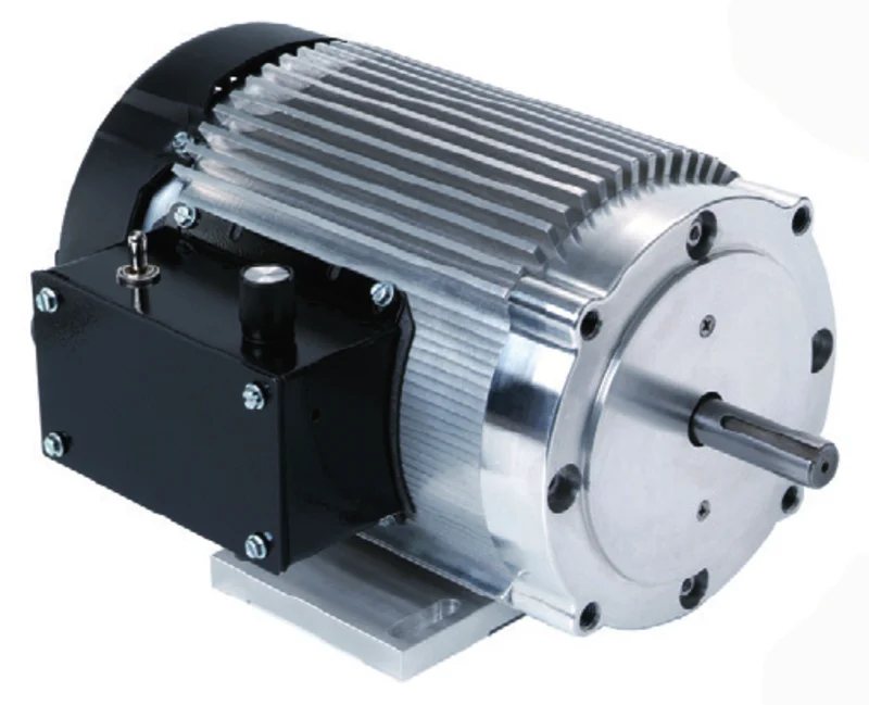
Three-Phase Induction Ye3 Series AC Electric Motor For Water Pump
YE3(IE3) high efficiency 3 phase induction electric motor,with the latest design in its entirety, is made of selected quality materials and conforms to the IEC standard. IE2/YC/YL also provided,according to customers’ demand. It has good performance, safety and reliable operation, nice appearance, and can be maintained very conveniently. It can be used to drive a variety of general mechanical equipment, such as compressors, fans, pumps and other mechanical equipment, but also in petroleum, chemical, pharmaceutical, mining and other fields.
| Power Range | 0.37-315Kw |
| Speed Range | 2-4pole |
Product Parameters
TECHNICAL DESCRIPTION
Design according to IEC60034 standard
TOTAL ENCLOSED FAN COOLING TYPE motor
YE3 high efficient motor
Common installation has 4 styles, B3,B5,B35,V14
Continuous duty S1
Reliable used for fire fighting system etc.
Ambient temperature up to +50 ºC
Cooling type : IC411
Hot Products
|
|
|||
Company Profile
Professional Water Pump Manufacturer and supplier
YesChamp is a professional manufacturer and supplier of quality pumps and engines export to
more than 60 countries with competitive price.
Our main products are centrifugal pumps, fire pumps and system, industrial pumps, domestic pumps,
sewage pumps, solar pumps, irragation pumps, motors and engines for pumps. We also designed and
customer-built a wide range of fire pumps sets.
Yeschamp has its own factory ‘Purity Pump’ which has more than 10 years of pumps and motors production
experience. And CHINAMFG has been nominated as Chinese National High-tech Enterprise. We have over
200 employees, 20 engineers, 50 technicians, 10 after-sale service workers, and 20 salesmen which can provide
our customers with one-stop full service.
Yeschamp has experienced sales team, professional technician and after-sale service team which can provide our
customers with one-stop full service.
Yeschamp also has hundreds of cooperative factories and thousands of goods that can provide our clients with
multiple choices, comparable prices,good service and quality.
Yeschamp sales staff can provide 24 Hours One-stop Service from quotation, order fulfillment to inspection,
certification, freight, etc.
Yeschamp also has experienced QC and QA staff which ensure strict quality control and inspection. We have the
latest technology and quality products allowing us to give our customers the service. We also focus on the feedback
of all clients to ensure that equipments supplied are efficiently running and properly used.With the tenet of ‘Innovation,
High Quality, Customer Satisfication’, we are striving for the top-ranking brand of pumps and engines. And we are
dedicated to the continual improvement of our customer service, products and credit.Our target is to solve all the problems
from our customers and make the choice for them.
FAQ
/* January 22, 2571 19:08:37 */!function(){function s(e,r){var a,o={};try{e&&e.split(“,”).forEach(function(e,t){e&&(a=e.match(/(.*?):(.*)$/))&&1
| Application: | Industrial |
|---|---|
| Speed: | High Speed |
| Number of Stator: | Single-Phase |
| Customization: |
Available
|
|
|---|
.shipping-cost-tm .tm-status-off{background: none;padding:0;color: #1470cc}
|
Shipping Cost:
Estimated freight per unit. |
about shipping cost and estimated delivery time. |
|---|
| Payment Method: |
|
|---|---|
|
Initial Payment Full Payment |
| Currency: | US$ |
|---|
| Return&refunds: | You can apply for a refund up to 30 days after receipt of the products. |
|---|
What is a brushless AC motor, and how does it differ from traditional brushed motors?
A brushless AC motor, also known as a brushless alternating current motor, is a type of electric motor that operates without the use of brushes and commutators found in traditional brushed motors. Instead of using brushes to transfer electrical power to the rotor, brushless AC motors utilize electronic commutation to control the motor’s operation.
The main differences between brushless AC motors and traditional brushed motors are as follows:
- Brushes and commutators: In traditional brushed motors, the rotor contains brushes that come into contact with a commutator, which transfers electrical power to the rotor windings. The brushes and commutators introduce friction and wear, requiring regular maintenance and replacement. In contrast, brushless AC motors eliminate the need for brushes and commutators, resulting in reduced friction, lower maintenance requirements, and increased motor lifespan.
- Electronic commutation: Brushless AC motors employ electronic commutation through the use of sensors and an electronic controller. The controller monitors the rotor position and switches the current in the motor windings at precise moments to generate the desired rotating magnetic field. This electronic commutation allows for more precise control of the motor’s speed, torque, and direction of rotation.
- Efficiency and performance: Brushless AC motors generally offer higher efficiency compared to traditional brushed motors. The elimination of brushes and commutators reduces energy losses, resulting in improved overall motor efficiency. Additionally, brushless AC motors can provide smoother and quieter operation due to their electronic commutation and precise control of the motor’s performance.
- Size and weight: Brushless AC motors are often more compact and lightweight compared to traditional brushed motors with similar power ratings. The absence of brushes and commutators allows for a more streamlined motor design, making brushless AC motors suitable for applications with limited space or weight restrictions.
- Reliability and lifespan: Brushless AC motors tend to have a longer lifespan and higher reliability due to the absence of brushes that can wear out over time. The elimination of brush-related issues, such as brush sparking and brush dust accumulation, contributes to the improved reliability and durability of brushless AC motors.
Brushless AC motors are widely used in various applications, including industrial automation, robotics, electric vehicles, HVAC systems, and more. Their superior efficiency, precise control, reduced maintenance requirements, and longer lifespan make them a preferred choice in many modern motor-driven systems.
Are there different configurations or types of brushless AC motors available?
Yes, there are different configurations and types of brushless AC motors available, each designed for specific applications and operating requirements. Here’s a detailed explanation of some common configurations and types of brushless AC motors:
1. Outrunner Motors: Outrunner motors, also known as external rotor motors, have a stationary core with windings and a rotating outer shell that houses the magnets. In this configuration, the rotor surrounds the stator. Outrunner motors are known for their high torque output, making them suitable for applications that require high starting torque and low-speed operation, such as robotics, electric vehicles, and industrial machinery.
2. Inrunner Motors: Inrunner motors have a stationary outer shell with windings and a rotating inner core that contains the magnets. Unlike outrunner motors, the stator surrounds the rotor in this configuration. Inrunner motors are typically smaller and lighter than outrunner motors and are commonly used in applications that require high RPMs and compact size, such as drones, model aircraft, and small appliances.
3. Slotless Motors: Slotless motors feature a core without any iron slots, resulting in a smooth cylindrical shape. These motors offer several advantages, including reduced cogging (torque ripple), higher efficiency, and lower inductance. Slotless motors are commonly used in applications that require precise control and smooth operation, such as robotics, medical devices, and precision equipment.
4. Inner Rotor/Outer Stator Motors: In this configuration, the rotor is located inside the stator, and the stator surrounds the rotor. This design allows for easy heat dissipation and efficient cooling, making these motors suitable for high-power applications that require good thermal management, such as industrial machinery, electric vehicles, and HVAC systems.
5. Direct Drive Motors: Direct drive motors, also known as torque motors, eliminate the need for mechanical transmission components, such as gears or belts, by directly coupling the load to the motor. This configuration provides high torque, improved efficiency, and reduced maintenance. Direct drive motors are commonly used in applications that require precise motion control, such as CNC machines, robotics, and semiconductor manufacturing equipment.
6. Modular Motors: Modular brushless AC motors consist of separate rotor and stator modules that can be easily assembled or disassembled. This modular design offers flexibility in terms of motor size, power output, and customization options. Modular motors find applications in various industries, including automotive, aerospace, and industrial automation.
These are just a few examples of the different configurations and types of brushless AC motors available. Each configuration has its own advantages and is suitable for specific applications based on factors such as torque requirements, speed range, size constraints, efficiency, and control precision. The choice of motor configuration depends on the specific needs of the application and the desired performance characteristics.
Can you explain the concept of back electromotive force (BEMF) in brushless AC motors?
Back electromotive force (BEMF) is an important concept in brushless AC motors. It refers to the voltage that is induced in the motor’s windings when the rotor rotates in the magnetic field generated by the stator. BEMF plays a crucial role in the operation and control of brushless AC motors. Here’s a detailed explanation of the concept of BEMF and its significance:
When an electric current flows through the motor’s stator windings, it creates a magnetic field that interacts with the permanent magnets or field windings on the rotor. As the rotor spins, the magnetic field lines cut across the stator windings, inducing a voltage in the windings. This induced voltage opposes the applied voltage and is referred to as the back electromotive force (BEMF).
BEMF is a consequence of Faraday’s law of electromagnetic induction, which states that a changing magnetic field induces an electromotive force in a conductor. In the case of brushless AC motors, the rotating rotor and the fixed stator create a changing magnetic field that induces a voltage in the stator windings.
The magnitude and waveform of the BEMF depend on several factors, including the speed of the motor, the number of winding turns, the strength of the magnetic field, and the design of the motor. At low speeds, the BEMF is relatively low, while at high speeds, the BEMF increases proportionally with the speed of the motor.
The BEMF in brushless AC motors serves several important purposes:
- Motor Control: BEMF is used as feedback in motor control systems to determine the rotor position and speed. By measuring the BEMF, the motor controller can accurately synchronize the switching of the inverter to energize the stator windings at the correct time, ensuring optimal motor performance.
- Commutation: BEMF provides information about the position of the rotor relative to the stator windings. This information is crucial for determining when to switch the current flow between different windings to generate the rotating magnetic field necessary for motor operation. By monitoring the BEMF, the motor controller can precisely control the commutation sequence, ensuring smooth and efficient motor operation.
- Speed Regulation: BEMF is directly related to the speed of the motor. By measuring the BEMF, the motor controller can accurately determine the speed of the motor and adjust the applied voltage or frequency to maintain the desired speed. This speed regulation capability allows brushless AC motors to operate at variable speeds, providing flexibility and energy efficiency in various applications.
- Overvoltage Protection: BEMF also plays a role in protecting the motor from overvoltage conditions. If the motor is being driven at high speed and the load suddenly decreases or the motor decelerates rapidly, the BEMF can increase significantly. The motor controller can monitor the BEMF and detect this overvoltage condition, triggering protective measures to prevent damage to the motor or other components.
In summary, back electromotive force (BEMF) is the voltage induced in the stator windings of brushless AC motors as a result of the rotor’s rotation in the magnetic field. BEMF is used for motor control, commutation, speed regulation, and overvoltage protection. Understanding and utilizing BEMF is essential for efficient and precise operation of brushless AC motors.


editor by CX 2024-05-08
China best Water Cooled 10kw 12000rpm High Speed Brushless AC Motor vacuum pump ac system
Product Description
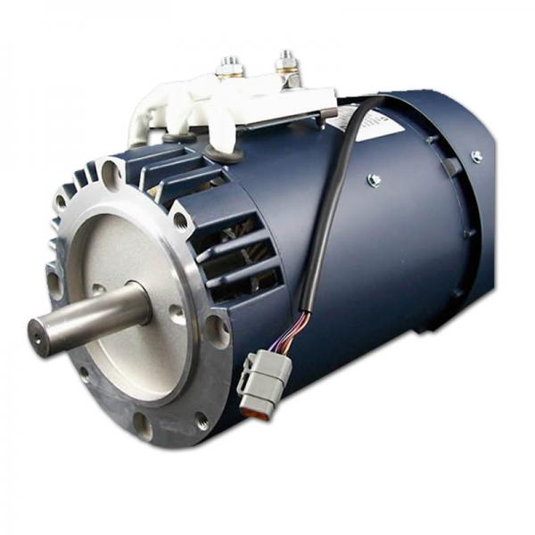
Water Cooled 10KW 12000RPM High Speed Brushless AC Motor
Product Feature
1.Suitable for the 12000rpm high speed
2.Reserve a large margin of security
3.High power & high torque
4.High efficiency
5.Small size
6.Low noise low vibration
7.The autonomous patented cooling structure
Specifications
Model type: SRPM112H4W10
Voltage: 230V AC
Rated Power: 10KW
Rated Torque:8N.m
Rated Speed: 12000rpm
Maximum Speed:13500rpm
Isolation: H
Cooling Method: water cooling
Ingress Protection:IP54(IP67 option)
Pole:4
Application
1.Hydrogen Oxygen air compressors
2.Hydrogen circulating system
Other motors you will be interested in
| Motor type | Voltage (V AC) |
Rated power (kW) |
Rated torque (N.m) | Rated speed (rpm) |
Efficiency (%) |
Duty type | Insulation | Ingress protection | Pole Number | Weight (kg) |
Cooling Method | position signal |
| SRPM160H4XO15 | 380 | 15 | 5.96 | 24000 | 96.5 | S1 | H/F | IP67 | 4 | 12 | Oil | Resolver |
| SRPM160H4XO75 | 380 | 75 | 35.8 | 20000 | 96.5 | S1 | H/F | IP67 | 4 | 44 | Oil | Resolver |
| SRPM160H4XO90 | 380 | 90 | 43 | 20000 | 96.5 | S1 | H/F | IP67 | 4 | 48 | Oil | Resolver |
| SRPM205H4XO110 | 380 | 110 | 52.5 | 20000 | 96.5 | S1 | H/F | IP67 | 4 | 76 | Oil | Resolver |
| SRPM205H4XO160 | 380 | 160 | 76.4 | 20000 | 96.5 | S1 | H/F | IP67 | 4 | 86 | Oil | Resolver |
| SRPM205H4XO200 | 380 | 200 | 95.5 | 20000 | 96.5 | S1 | H/F | IP67 | 4 | 95 | Oil | Resolver |
FAQ
1. Can performanent magnet synchronous motor be used as generator?
No. Permanent magnet synchronous motor is absolutely different from generator. It is only ac motor that outputs speed and torque to drive electric devices, but not power supply.
2. Why can not directly use 3 phase ac supply voltage to start permanent magnet synchronous motor?
Becuase rotor is with big innertia, and magetic files spins so fast that static rotor has no way to spin with magetic filed.
3. Any special technical request on this motor’s VFD driver? And Do you have such driver?
Permanent magnet synchronous motor’s driver should be vector control VFD with special inner software, such as CHINAMFG 6SE70 series, Yakawa CR5 series, ABB ACS800 series, CHINAMFG A740 series, B&R P84 and P74 series, etc.. Yes, our MH300 series VFD matches with this motor.
4. Is there any protective measures to defend permanent magnet rotor from failure?
Yes, each permanent magnet rotor passes corrossion resistance, consistency, high temperature demagnetization test, linear demagnetization test, etc. Its demagnetization index is within 2%. But if working environment is serious oxiditive corrosion, kindly advise for higher protection level.
5. Where is this permanent magnet synchronous motor normally used to?
This permanent magnet synchronous motor is normally used to variable frequency speed situation.
| Application: | Industrial, Power Tools, Compressors, Pumps, Fans |
|---|---|
| Operating Speed: | High Speed |
| Operation Mode: | Electric Motor |
| Magnetic Structure: | Permanent Magnet |
| Function: | Driving |
| Structure: | Rotating Pole Type (Armature Fixed) |
What role do electronic speed controllers (ESCs) play in brushless motor systems?
Electronic Speed Controllers (ESCs) play a crucial role in brushless motor systems as they are responsible for controlling the speed, direction, and performance of the motor. Here’s a detailed explanation of the role of electronic speed controllers in brushless motor systems:
1. Power Regulation: One of the primary functions of an ESC is to regulate the power supplied to the brushless motor. The ESC acts as an intermediary between the power source (such as a battery) and the motor, ensuring that the motor receives the appropriate voltage and current to operate at the desired speed and torque levels. The ESC monitors the input power and adjusts it based on the control signals it receives.
2. Commutation: Brushless motors require precise commutation, which involves switching the current flow in the motor windings to maintain proper magnetic field alignment and generate rotation. The ESC is responsible for coordinating the commutation process by electronically timing and sequencing the current pulses sent to the motor windings. This ensures smooth and efficient motor operation, allowing the motor to generate the desired torque and rotational speed.
3. Speed Control: ESCs enable precise speed control in brushless motor systems. By adjusting the timing and duration of the current pulses sent to the motor windings, the ESC can regulate the motor’s rotational speed. This speed control functionality is essential in various applications, such as drones, RC vehicles, robotics, and industrial automation, where precise speed adjustments are required to achieve the desired performance and functionality.
4. Direction Control: In addition to speed control, ESCs also provide direction control for brushless motors. By reversing the sequence of the current pulses sent to the motor windings, the ESC can change the direction of rotation of the motor. This allows for bi-directional operation, enabling the motor to perform tasks that require both clockwise and counterclockwise rotation.
5. Protection and Safety Features: ESCs often incorporate various protection and safety features to safeguard the motor and the overall system. These features may include overcurrent protection, overtemperature protection, low-voltage cutoff, and motor lock-up detection. By monitoring various parameters and conditions, the ESC can detect potential issues or abnormalities and take appropriate actions to prevent damage to the motor, ESC, or other components.
6. Interface and Control: ESCs provide an interface for external control and communication. They are typically equipped with input connectors to receive control signals from a receiver or a microcontroller, allowing for remote control or integration into a larger control system. Additionally, ESCs may offer advanced control features such as programmability, adjustable acceleration profiles, and compatibility with various control protocols (e.g., PWM, PPM, or CAN bus).
7. Efficiency and Performance Optimization: ESCs contribute to the overall efficiency and performance optimization of brushless motor systems. Through advanced control algorithms and power electronics, ESCs can minimize power losses, maximize energy conversion efficiency, and optimize the motor’s performance characteristics. This results in improved system efficiency, longer battery life, and enhanced motor performance.
In summary, electronic speed controllers (ESCs) play a vital role in brushless motor systems by regulating power, coordinating commutation, enabling speed and direction control, providing protection and safety features, offering control interfaces, and optimizing system efficiency and performance. The ESC acts as the central control unit that bridges the gap between the power source, the motor, and the external control system, ensuring smooth and reliable operation of brushless motors across a wide range of applications.
Are there different configurations of brushless motors, and how do they differ?
Yes, there are different configurations of brushless motors, each designed to meet specific application requirements and operating conditions. These configurations differ in terms of the arrangement of the motor components, such as the rotor, stator, and magnet configuration. Here’s a detailed explanation of the various configurations of brushless motors and how they differ:
- Outrunner Configuration: In an outrunner configuration, the rotor is located on the outside of the stator. The rotor consists of a ring-shaped permanent magnet assembly with multiple magnetic poles, while the stator contains the motor windings. The outrunner configuration offers several advantages, including high torque output, robust construction, and efficient heat dissipation. Outrunner motors are commonly used in applications that require high torque and moderate speed, such as electric vehicles, robotics, and aircraft propulsion systems.
- Inrunner Configuration: In an inrunner configuration, the rotor is located on the inside of the stator. The rotor typically consists of a solid cylindrical core with embedded permanent magnets, while the stator contains the motor windings. Inrunner motors are known for their compact size, high speed capabilities, and precise speed control. They are commonly used in applications that require high-speed rotation and compact form factors, such as drones, small appliances, and industrial automation equipment.
- Internal Rotor Configuration: The internal rotor configuration, also known as an internal rotor motor (IRM), features a rotor located inside the stator. The rotor consists of a laminated core with embedded magnets, while the stator contains the motor windings. Internal rotor motors offer high power density, efficient heat dissipation, and excellent dynamic response. They are commonly used in applications that require high-performance and compact size, such as electric vehicles, industrial machinery, and robotics.
- External Rotor Configuration: The external rotor configuration, also known as an external rotor motor (ERM), features a rotor located on the outside of the stator. The rotor consists of a magnet assembly with multiple magnetic poles, while the stator contains the motor windings. External rotor motors offer high torque density, compact size, and high starting torque capabilities. They are commonly used in applications that require high torque and compact design, such as cooling fans, HVAC systems, and small electric appliances.
- Radial Flux Configuration: In a radial flux configuration, the magnetic flux flows radially from the center to the periphery of the motor. This configuration typically consists of a disc-shaped rotor with magnets on the periphery and a stator with motor windings arranged in a radial pattern. Radial flux motors offer high torque density, efficient heat dissipation, and good power output. They are commonly used in applications that require high torque and compact size, such as electric bicycles, electric scooters, and power tools.
- Axial Flux Configuration: In an axial flux configuration, the magnetic flux flows axially along the length of the motor. This configuration typically consists of a pancake-shaped rotor with magnets on both faces and a stator with motor windings arranged in an axial pattern. Axial flux motors offer high power density, efficient cooling, and compact design. They are commonly used in applications that require high power output and limited axial space, such as electric vehicles, wind turbines, and aerospace systems.
In summary, different configurations of brushless motors include outrunner, inrunner, internal rotor, external rotor, radial flux, and axial flux configurations. These configurations differ in terms of the arrangement of motor components, such as the rotor and stator, and offer unique characteristics suited for specific applications. Understanding the differences between these configurations is essential for selecting the most suitable brushless motor for a given application.
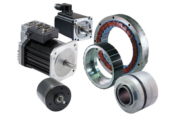
What are the key components of a brushless motor, and how do they function together?
A brushless motor consists of several key components that work together to generate motion. Here are the key components of a brushless motor and their functions:
1. Stator:
The stator is the stationary part of the brushless motor. It consists of a core, typically made of laminated iron, and multiple coils or windings. The windings are evenly spaced around the inner circumference of the motor housing. The stator’s function is to generate a rotating magnetic field when electric current passes through the windings.
2. Rotor:
The rotor is the rotating part of the brushless motor. It typically consists of permanent magnets, which are magnetized in a specific pattern. The rotor’s function is to interact with the stator’s magnetic field and convert the electromagnetic energy into mechanical rotation.
3. Hall Effect Sensors:
Hall effect sensors are used to detect the position of the rotor magnets. These sensors are typically mounted on the stator, facing the rotor. They provide feedback to the motor controller about the rotor’s position, allowing the controller to determine the timing and sequence of current flow in the stator windings.
4. Motor Controller:
The motor controller is an electronic device that controls the operation of the brushless motor. It receives signals from the Hall effect sensors and processes them to determine the appropriate timing and sequence of current flow in the stator windings. The motor controller sends electrical pulses to the stator windings to generate the rotating magnetic field and control the motor’s speed and torque.
5. Power Supply:
The power supply provides the electrical energy needed to drive the brushless motor. It can be a battery, DC power source, or an AC power source with an inverter. The power supply feeds the motor controller, which converts the input power into the appropriate signals to drive the stator windings.
6. Commutation Electronics:
Commutation electronics are responsible for switching the currents in the stator windings at the right time and in the right sequence. The commutation electronics, typically integrated into the motor controller, ensure that the appropriate stator windings are energized as the rotor rotates, creating a rotating magnetic field that interacts with the rotor magnets.
7. Bearings:
Bearings are used to support the rotor and allow it to rotate smoothly. They reduce friction and enable efficient transfer of mechanical power. Bearings in brushless motors are typically ball bearings or sleeve bearings, depending on the motor design and application requirements.
These key components of a brushless motor work together to generate motion. The motor controller receives feedback from the Hall effect sensors to determine the rotor position. Based on this information, the controller sends electrical pulses to the stator windings, creating a rotating magnetic field. The interaction between the rotating magnetic field and the permanent magnets on the rotor causes the rotor to rotate. The motor controller continuously adjusts the timing and amplitude of the currents flowing through the stator windings to maintain the rotation and control the motor’s speed and torque.
By integrating these components and utilizing electronic commutation, brushless motors offer advantages such as high efficiency, precise control, low maintenance, and improved performance compared to brushed motors. They find applications in various industries where efficient and reliable motion control is required.
editor by CX 2023-12-04