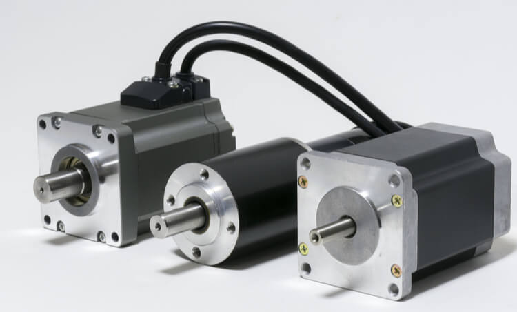
Product Description
Brushed or Brushless DC Motors, Customized Specifications, OEM/ODM
Option for :
Customized shaft, performance, voltage, mounting, lead wires..
Option for :
Electric Brake, Planetary Gearbox, Worm Gearbox, Encoder, Controller Integrated
1. BRUSHED DC MOTOR :
Voltage 12v, 24v, 36v, 48v, upto 310vdc
power 5w to 1000w
speed 1pm upto 10000rpm
Dia. 30mm, 32mm, 36mm, 38mm, 42mm, 52mm, 54mm, 63mm, 70mm, 76mm, 80mm, 90mm, 110mm
Belows are some typical models,
2. BRUSHLESS DC MOTOR :
Voltage 12v, 24v, 36v, 48v, upto 380vdc
power 5w to 2000w
speed 1pm upto 15000rpm
Size 28mm, 30mm, 36mm, 42mm, 57mm, 60mm, 63mm, 70mm, 80mm, 86mm, 110mm
| Bearing | High quality ball bearing |
| Poles | 4- poles 8-poles 12-poles |
| Protection class | IP40 IP55 option |
| Insulation class | class: F |
Belows are some typical models,
Below are only some typical models for reference.
63ZYT Series Permanent magnet Brushed Dc Motors
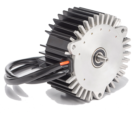
57HBL Series Brushless Dc Motors
56JXE300K. 63ZYT Series Dc Planetary Gear Motor
56JXE300K. 57HBL Series Brushless Dc Planetary Gear Motor
/* January 22, 2571 19:08:37 */!function(){function s(e,r){var a,o={};try{e&&e.split(“,”).forEach(function(e,t){e&&(a=e.match(/(.*?):(.*)$/))&&1
| Application: | Universal, Industrial, Household Appliances, Car, Power Tools, Machine, Robot |
|---|---|
| Operating Speed: | Constant Speed |
| Excitation Mode: | Pm |
| Function: | Control, Driving |
| Casing Protection: | Closed Type |
| Number of Poles: | 2 |
| Customization: |
Available
|
|
|---|
How do brushless motors compare to brushed motors in terms of lifespan and reliability?
When comparing brushless motors to brushed motors, there are notable differences in terms of lifespan and reliability. Here’s a detailed explanation of how brushless motors compare to brushed motors in these aspects:
1. Lifespan:
Brushed motors typically have a shorter lifespan compared to brushless motors. This is primarily due to the mechanical wear and tear associated with brushed motors. In brushed motors, the brushes and commutator make physical contact, causing friction, heat generation, and eventual wear. Over time, the brushes wear down and the commutator may become worn or damaged, leading to degraded motor performance and eventual failure. On the other hand, brushless motors do not have brushes or commutators, eliminating the mechanical wear components. As a result, brushless motors generally have a longer lifespan and can operate for thousands of hours with minimal maintenance.
2. Reliability:
Brushless motors are generally considered more reliable than brushed motors. The absence of brushes and commutators in brushless motors reduces the risk of failure due to mechanical wear and associated issues like brush sparking and arcing. The elimination of these moving parts also leads to reduced friction, less heat generation, and lower chances of electrical or mechanical failures. Additionally, brushless motors often benefit from advanced control systems that can monitor and protect against various operating conditions, enhancing their overall reliability.
3. Operating Conditions:
Brushless motors are better suited for demanding operating conditions compared to brushed motors. The absence of brushes and commutators in brushless motors means there are no physical contacts that can generate sparks or cause electrical arcing. This makes brushless motors more suitable for applications where sparks or electrical noise can be problematic, such as in explosive or sensitive electronic environments. Furthermore, brushless motors can operate at higher speeds and handle higher torque loads than brushed motors, making them more versatile in a wide range of applications.
4. Maintenance:
Brushless motors generally require less maintenance compared to brushed motors. Brushed motors often require periodic maintenance to replace worn-out brushes and address commutator issues. Additionally, the presence of brushes can lead to carbon dust buildup, requiring regular cleaning and maintenance. In contrast, brushless motors have no brushes or commutators to replace or clean, significantly reducing the maintenance requirements. However, it’s important to note that brushless motors may still require periodic inspections, especially for cooling systems or bearings, to ensure optimal performance and reliability.
5. Efficiency:
Brushless motors are typically more efficient than brushed motors. The absence of brushes and commutators in brushless motors reduces energy losses associated with friction and electrical resistance. This improved efficiency results in several benefits, such as reduced power consumption, longer battery life (in battery-powered applications), and less heat generation. Brushless motors are known for their high power-to-weight ratio and can deliver higher torque output per unit of input power compared to brushed motors.
In summary, brushless motors generally offer a longer lifespan and higher reliability compared to brushed motors. The absence of brushes and commutators reduces mechanical wear and associated failures, making brushless motors more durable. They are better suited for demanding operating conditions, require less maintenance, and offer improved efficiency. These factors have made brushless motors increasingly popular in various applications, including robotics, electric vehicles, industrial automation, and aerospace, where reliability and longevity are essential.
What is the significance of commutation in brushless motor operation, and how is it achieved?
Commutation is a critical aspect of brushless motor operation as it determines the timing and sequence of current flow in the motor windings. It is the process by which the motor’s magnetic field is switched to generate continuous rotation. The significance of commutation lies in its ability to maintain proper alignment between the magnetic field produced by the stator and the rotor’s permanent magnets, resulting in smooth and efficient motor operation. Here’s a detailed explanation of the significance of commutation in brushless motor operation and how it is achieved:
1. Magnetic Field Alignment: Commutation ensures that the magnetic field produced by the motor’s stator windings is properly aligned with the permanent magnets on the rotor. This alignment is crucial for generating the necessary torque to drive the rotor and produce rotation. By switching the current flow in the motor windings at the right time and in the right sequence, commutation ensures that the stator’s magnetic field interacts effectively with the rotor’s magnets, producing continuous and smooth rotation.
2. Efficient Power Conversion: Commutation plays a vital role in efficient power conversion within the brushless motor. As the current flows through the motor windings, commutation switches the current path to maintain the desired direction of rotation. By timely switching the current flow, commutation minimizes power losses and maximizes the energy transfer between the power supply and the motor. This efficient power conversion results in improved motor performance, higher energy efficiency, and reduced heat generation.
3. Elimination of Brushes and Commutators: Unlike brushed motors that rely on mechanical brushes and commutators for current switching, brushless motors achieve commutation electronically. This eliminates the need for brushes and commutators, which are prone to wear, friction, and electrical arcing. By replacing these mechanical components with solid-state electronic commutation, brushless motors offer several advantages, including reduced maintenance requirements, longer lifespan, and improved reliability.
4. Precise Speed Control: Commutation in brushless motors enables precise speed control. By accurately timing and sequencing the current flow in the motor windings, the control system of a brushless motor can regulate the motor’s rotational speed. This precise speed control is crucial in applications that require specific speed requirements, such as robotics, electric vehicles, and industrial automation.
5. Commutation Methods: Brushless motors achieve commutation through various methods, the most common being sensor-based commutation and sensorless commutation. Sensor-based commutation utilizes position sensors, such as Hall effect sensors or encoders, to detect the rotor’s position and determine the appropriate timing and sequence of current switching. Sensorless commutation, on the other hand, estimates the rotor position based on the back electromotive force (EMF) generated in the motor windings. Advanced control algorithms and signal processing techniques are employed to accurately estimate the rotor position and achieve precise commutation without the need for additional sensors.
In summary, commutation is of significant importance in brushless motor operation. It ensures proper alignment of the magnetic fields, enables efficient power conversion, eliminates mechanical wear components, allows for precise speed control, and contributes to the overall performance and reliability of brushless motors. Through sensor-based or sensorless commutation methods, brushless motors achieve accurate and timely switching of current flow, resulting in smooth rotation and optimal motor performance.
Can you explain the working principle of brushless motors and how they generate motion?
Brushless motors operate based on the principles of electromagnetism and electronic commutation. Here’s an explanation of the working principle of brushless motors and how they generate motion:
1. Stator and Rotor:
A brushless motor consists of two main components: a stationary stator and a rotating rotor. The stator contains multiple coils or windings arranged in a specific pattern. These windings are typically made of copper wire and are evenly spaced around the inner circumference of the motor housing. The rotor, on the other hand, contains permanent magnets that are magnetized in a specific pattern.
2. Electronic Commutation:
The key difference between brushless motors and brushed motors is the method of commutation. In brushed motors, commutation is achieved mechanically through brushes and a commutator. However, in brushless motors, commutation is electronic. The commutation process is managed by an external controller or electronic speed controller (ESC).
3. Rotor Position Detection:
To determine the rotor’s position, brushless motors use sensors or Hall effect devices embedded in the stator. These sensors detect the position of the permanent magnets on the rotor as it rotates. The sensor information is sent to the controller, which uses it to determine the timing and sequence of current flow in the stator windings.
4. Current Distribution:
Based on the rotor position information, the controller determines which stator windings need to be energized to generate the desired motion. The controller then sends electric currents to the appropriate windings in a specific sequence. By energizing different windings at different times, the controller can create a rotating magnetic field in the stator.
5. Magnetic Field Interaction:
As the rotating magnetic field is generated in the stator, it interacts with the permanent magnets on the rotor. The interaction between the rotating magnetic field and the permanent magnets causes the rotor to rotate. The controller continuously adjusts the timing and amplitude of the currents flowing through the stator windings to maintain the rotation and control the motor’s speed and torque.
6. Continuous Rotation:
Brushless motors achieve continuous rotation by continuously updating the rotor position using the sensors and adjusting the current flow in the stator windings accordingly. The electronic commutation process ensures that the currents are switched at the right time and in the right sequence to maintain the rotation and provide precise control over the motor’s operation.
By using electronic commutation and precise control over the currents in the stator windings, brushless motors generate motion with high efficiency, reliability, and accuracy. They offer advantages such as higher speed capabilities, smoother operation, reduced maintenance requirements, and improved overall performance compared to brushed motors. These characteristics make brushless motors widely used in various applications, ranging from small consumer electronics to large industrial machinery.


editor by CX 2024-05-09
China supplier Customizable Electric Brushed Brushless DC Motor 12V 18V 24V 36V 48V 310V PMDC/BLDC Planetary/Worm Gear Motor 12 24 36 48 Volt 15W 50W 100W 200W 300W 500W 800W vacuum pump and compressor
Product Description
Brushed or Brushless DC Motors, Customized Specifications, OEM/ODM
Option for :
Customized shaft, performance, voltage, mounting, lead wires..
Option for :
Electric Brake, Planetary Gearbox, Worm Gearbox, Encoder, Controller Integrated
1. BRUSHED DC MOTOR :
Voltage 12v, 24v, 36v, 48v, upto 310vdc
power 5w to 1000w
speed 1pm upto 10000rpm
Dia. 30mm, 32mm, 36mm, 38mm, 42mm, 52mm, 54mm, 63mm, 70mm, 76mm, 80mm, 90mm, 110mm
Belows are some typical models,
2. BRUSHLESS DC MOTOR :
Voltage 12v, 24v, 36v, 48v, upto 380vdc
power 5w to 2000w
speed 1pm upto 15000rpm
Size 28mm, 30mm, 36mm, 42mm, 57mm, 60mm, 63mm, 70mm, 80mm, 86mm, 110mm
| Bearing | High quality ball bearing |
| Poles | 4- poles 8-poles 12-poles |
| Protection class | IP40 IP55 option |
| Insulation class | class: F |
Belows are some typical models,
Below are only some typical models for reference.
63ZYT Series Permanent magnet Brushed Dc Motors
57HBL Series Brushless Dc Motors
56JXE300K. 63ZYT Series Dc Planetary Gear Motor
56JXE300K. 57HBL Series Brushless Dc Planetary Gear Motor
/* January 22, 2571 19:08:37 */!function(){function s(e,r){var a,o={};try{e&&e.split(“,”).forEach(function(e,t){e&&(a=e.match(/(.*?):(.*)$/))&&1
| Application: | Universal, Industrial, Household Appliances, Car, Power Tools, Machine, Robot |
|---|---|
| Operating Speed: | Constant Speed |
| Excitation Mode: | Pm |
| Function: | Control, Driving |
| Casing Protection: | Closed Type |
| Number of Poles: | 2 |
| Customization: |
Available
|
|
|---|
Where can individuals find reliable information and resources for learning more about brushless motors?
Individuals seeking reliable information and resources to learn more about brushless motors have several options available. Here are some recommended sources:
1. Manufacturer Websites:
Visit the websites of reputable brushless motor manufacturers. Manufacturers often provide detailed information about their products, including specifications, application guidelines, technical documentation, and educational resources. These websites can be a valuable source of accurate and up-to-date information about brushless motors.
2. Industry Associations and Organizations:
Explore industry associations and organizations related to electric motors, automation, or specific applications of brushless motors. These associations often provide educational materials, technical publications, webinars, and conferences that cover various aspects of motor technology. Examples include the Institute of Electrical and Electronics Engineers (IEEE), the American Society of Mechanical Engineers (ASME), or industry-specific associations like the Robotics Industries Association (RIA) or the Electric Motor Education and Research Foundation (EMERF).
3. Technical Forums and Online Communities:
Participate in technical forums and online communities focused on motors and related technologies. Platforms like Stack Exchange, Reddit, or specialized engineering forums often have dedicated sections where individuals can ask questions, learn from experts, and access valuable resources. Engaging with these communities can provide insights into real-world experiences and practical knowledge about brushless motors.
4. Books and Publications:
Consult books, textbooks, and technical publications that cover electric motors and motor control theory. Look for titles that specifically address brushless motor technology or broader topics such as electromechanical systems, power electronics, or mechatronics. Libraries, online bookstores, and academic institutions are good sources for finding relevant publications.
5. Online Tutorials and Courses:
Explore online tutorials and courses offered by educational platforms, engineering schools, or specialized training providers. Platforms such as Coursera, Udemy, or Khan Academy may offer courses related to electric motors, motor control, or mechatronics. These resources often provide structured learning experiences with video lectures, practical exercises, and assessments.
6. Research Papers and Technical Journals:
Access research papers and technical journals focused on electrical engineering, motor technology, or related fields. Platforms like IEEE Xplore, ResearchGate, or academic databases provide access to a wide range of scholarly articles and technical papers. These sources can offer in-depth knowledge about the latest advancements, research findings, and technical details related to brushless motors.
7. Industry Trade Shows and Exhibitions:
Attend industry trade shows and exhibitions that feature motor manufacturers, suppliers, and technology providers. These events often showcase the latest products, innovations, and advancements in motor technology. They also provide opportunities to interact with industry experts, attend technical presentations, and gather valuable information about brushless motors.
8. Online Product Catalogs and Datasheets:
Review online product catalogs and datasheets provided by motor manufacturers. These documents typically contain detailed specifications, performance data, and application notes for specific motor models. They can help individuals understand the capabilities, limitations, and features of different brushless motors.
Remember to critically evaluate the information obtained from various sources and cross-reference multiple resources to ensure accuracy and reliability. Brushless motor technology is a dynamic field, so staying updated with the latest research and industry developments is essential for gaining comprehensive knowledge.
Are there different configurations of brushless motors, and how do they differ?
Yes, there are different configurations of brushless motors, each designed to meet specific application requirements and operating conditions. These configurations differ in terms of the arrangement of the motor components, such as the rotor, stator, and magnet configuration. Here’s a detailed explanation of the various configurations of brushless motors and how they differ:
- Outrunner Configuration: In an outrunner configuration, the rotor is located on the outside of the stator. The rotor consists of a ring-shaped permanent magnet assembly with multiple magnetic poles, while the stator contains the motor windings. The outrunner configuration offers several advantages, including high torque output, robust construction, and efficient heat dissipation. Outrunner motors are commonly used in applications that require high torque and moderate speed, such as electric vehicles, robotics, and aircraft propulsion systems.
- Inrunner Configuration: In an inrunner configuration, the rotor is located on the inside of the stator. The rotor typically consists of a solid cylindrical core with embedded permanent magnets, while the stator contains the motor windings. Inrunner motors are known for their compact size, high speed capabilities, and precise speed control. They are commonly used in applications that require high-speed rotation and compact form factors, such as drones, small appliances, and industrial automation equipment.
- Internal Rotor Configuration: The internal rotor configuration, also known as an internal rotor motor (IRM), features a rotor located inside the stator. The rotor consists of a laminated core with embedded magnets, while the stator contains the motor windings. Internal rotor motors offer high power density, efficient heat dissipation, and excellent dynamic response. They are commonly used in applications that require high-performance and compact size, such as electric vehicles, industrial machinery, and robotics.
- External Rotor Configuration: The external rotor configuration, also known as an external rotor motor (ERM), features a rotor located on the outside of the stator. The rotor consists of a magnet assembly with multiple magnetic poles, while the stator contains the motor windings. External rotor motors offer high torque density, compact size, and high starting torque capabilities. They are commonly used in applications that require high torque and compact design, such as cooling fans, HVAC systems, and small electric appliances.
- Radial Flux Configuration: In a radial flux configuration, the magnetic flux flows radially from the center to the periphery of the motor. This configuration typically consists of a disc-shaped rotor with magnets on the periphery and a stator with motor windings arranged in a radial pattern. Radial flux motors offer high torque density, efficient heat dissipation, and good power output. They are commonly used in applications that require high torque and compact size, such as electric bicycles, electric scooters, and power tools.
- Axial Flux Configuration: In an axial flux configuration, the magnetic flux flows axially along the length of the motor. This configuration typically consists of a pancake-shaped rotor with magnets on both faces and a stator with motor windings arranged in an axial pattern. Axial flux motors offer high power density, efficient cooling, and compact design. They are commonly used in applications that require high power output and limited axial space, such as electric vehicles, wind turbines, and aerospace systems.
In summary, different configurations of brushless motors include outrunner, inrunner, internal rotor, external rotor, radial flux, and axial flux configurations. These configurations differ in terms of the arrangement of motor components, such as the rotor and stator, and offer unique characteristics suited for specific applications. Understanding the differences between these configurations is essential for selecting the most suitable brushless motor for a given application.
What are the key components of a brushless motor, and how do they function together?
A brushless motor consists of several key components that work together to generate motion. Here are the key components of a brushless motor and their functions:
1. Stator:
The stator is the stationary part of the brushless motor. It consists of a core, typically made of laminated iron, and multiple coils or windings. The windings are evenly spaced around the inner circumference of the motor housing. The stator’s function is to generate a rotating magnetic field when electric current passes through the windings.
2. Rotor:
The rotor is the rotating part of the brushless motor. It typically consists of permanent magnets, which are magnetized in a specific pattern. The rotor’s function is to interact with the stator’s magnetic field and convert the electromagnetic energy into mechanical rotation.
3. Hall Effect Sensors:
Hall effect sensors are used to detect the position of the rotor magnets. These sensors are typically mounted on the stator, facing the rotor. They provide feedback to the motor controller about the rotor’s position, allowing the controller to determine the timing and sequence of current flow in the stator windings.
4. Motor Controller:
The motor controller is an electronic device that controls the operation of the brushless motor. It receives signals from the Hall effect sensors and processes them to determine the appropriate timing and sequence of current flow in the stator windings. The motor controller sends electrical pulses to the stator windings to generate the rotating magnetic field and control the motor’s speed and torque.
5. Power Supply:
The power supply provides the electrical energy needed to drive the brushless motor. It can be a battery, DC power source, or an AC power source with an inverter. The power supply feeds the motor controller, which converts the input power into the appropriate signals to drive the stator windings.
6. Commutation Electronics:
Commutation electronics are responsible for switching the currents in the stator windings at the right time and in the right sequence. The commutation electronics, typically integrated into the motor controller, ensure that the appropriate stator windings are energized as the rotor rotates, creating a rotating magnetic field that interacts with the rotor magnets.
7. Bearings:
Bearings are used to support the rotor and allow it to rotate smoothly. They reduce friction and enable efficient transfer of mechanical power. Bearings in brushless motors are typically ball bearings or sleeve bearings, depending on the motor design and application requirements.
These key components of a brushless motor work together to generate motion. The motor controller receives feedback from the Hall effect sensors to determine the rotor position. Based on this information, the controller sends electrical pulses to the stator windings, creating a rotating magnetic field. The interaction between the rotating magnetic field and the permanent magnets on the rotor causes the rotor to rotate. The motor controller continuously adjusts the timing and amplitude of the currents flowing through the stator windings to maintain the rotation and control the motor’s speed and torque.
By integrating these components and utilizing electronic commutation, brushless motors offer advantages such as high efficiency, precise control, low maintenance, and improved performance compared to brushed motors. They find applications in various industries where efficient and reliable motion control is required.
editor by CX 2024-05-09
China factory Customizable Electric Brushed Brushless DC Motor 12V 18V 24V 36V 48V 310V PMDC/BLDC Planetary/Worm Gear Motor 12 24 36 48 Volt 15W 50W 100W 200W 300W 500W 800W vacuum pump adapter
Product Description
Brushed or Brushless DC Motors, Customized Specifications, OEM/ODM
Option for :
Customized shaft, performance, voltage, mounting, lead wires..
Option for :
Electric Brake, Planetary Gearbox, Worm Gearbox, Encoder, Controller Integrated
1. BRUSHED DC MOTOR :
Voltage 12v, 24v, 36v, 48v, upto 310vdc
power 5w to 1000w
speed 1pm upto 10000rpm
Dia. 30mm, 32mm, 36mm, 38mm, 42mm, 52mm, 54mm, 63mm, 70mm, 76mm, 80mm, 90mm, 110mm
Belows are some typical models,
2. BRUSHLESS DC MOTOR :
Voltage 12v, 24v, 36v, 48v, upto 380vdc
power 5w to 2000w
speed 1pm upto 15000rpm
Size 28mm, 30mm, 36mm, 42mm, 57mm, 60mm, 63mm, 70mm, 80mm, 86mm, 110mm
| Bearing | High quality ball bearing |
| Poles | 4- poles 8-poles 12-poles |
| Protection class | IP40 IP55 option |
| Insulation class | class: F |
Belows are some typical models,
Below are only some typical models for reference.
63ZYT Series Permanent magnet Brushed Dc Motors
57HBL Series Brushless Dc Motors
56JXE300K. 63ZYT Series Dc Planetary Gear Motor
56JXE300K. 57HBL Series Brushless Dc Planetary Gear Motor
/* January 22, 2571 19:08:37 */!function(){function s(e,r){var a,o={};try{e&&e.split(“,”).forEach(function(e,t){e&&(a=e.match(/(.*?):(.*)$/))&&1
| Application: | Universal, Industrial, Household Appliances, Car, Power Tools, Machine, Robot |
|---|---|
| Operating Speed: | Constant Speed |
| Excitation Mode: | Pm |
| Function: | Control, Driving |
| Casing Protection: | Closed Type |
| Number of Poles: | 2 |
| Customization: |
Available
|
|
|---|
How do brushless motors compare to brushed motors in terms of lifespan and reliability?
When comparing brushless motors to brushed motors, there are notable differences in terms of lifespan and reliability. Here’s a detailed explanation of how brushless motors compare to brushed motors in these aspects:
1. Lifespan:
Brushed motors typically have a shorter lifespan compared to brushless motors. This is primarily due to the mechanical wear and tear associated with brushed motors. In brushed motors, the brushes and commutator make physical contact, causing friction, heat generation, and eventual wear. Over time, the brushes wear down and the commutator may become worn or damaged, leading to degraded motor performance and eventual failure. On the other hand, brushless motors do not have brushes or commutators, eliminating the mechanical wear components. As a result, brushless motors generally have a longer lifespan and can operate for thousands of hours with minimal maintenance.
2. Reliability:
Brushless motors are generally considered more reliable than brushed motors. The absence of brushes and commutators in brushless motors reduces the risk of failure due to mechanical wear and associated issues like brush sparking and arcing. The elimination of these moving parts also leads to reduced friction, less heat generation, and lower chances of electrical or mechanical failures. Additionally, brushless motors often benefit from advanced control systems that can monitor and protect against various operating conditions, enhancing their overall reliability.
3. Operating Conditions:
Brushless motors are better suited for demanding operating conditions compared to brushed motors. The absence of brushes and commutators in brushless motors means there are no physical contacts that can generate sparks or cause electrical arcing. This makes brushless motors more suitable for applications where sparks or electrical noise can be problematic, such as in explosive or sensitive electronic environments. Furthermore, brushless motors can operate at higher speeds and handle higher torque loads than brushed motors, making them more versatile in a wide range of applications.
4. Maintenance:
Brushless motors generally require less maintenance compared to brushed motors. Brushed motors often require periodic maintenance to replace worn-out brushes and address commutator issues. Additionally, the presence of brushes can lead to carbon dust buildup, requiring regular cleaning and maintenance. In contrast, brushless motors have no brushes or commutators to replace or clean, significantly reducing the maintenance requirements. However, it’s important to note that brushless motors may still require periodic inspections, especially for cooling systems or bearings, to ensure optimal performance and reliability.
5. Efficiency:
Brushless motors are typically more efficient than brushed motors. The absence of brushes and commutators in brushless motors reduces energy losses associated with friction and electrical resistance. This improved efficiency results in several benefits, such as reduced power consumption, longer battery life (in battery-powered applications), and less heat generation. Brushless motors are known for their high power-to-weight ratio and can deliver higher torque output per unit of input power compared to brushed motors.
In summary, brushless motors generally offer a longer lifespan and higher reliability compared to brushed motors. The absence of brushes and commutators reduces mechanical wear and associated failures, making brushless motors more durable. They are better suited for demanding operating conditions, require less maintenance, and offer improved efficiency. These factors have made brushless motors increasingly popular in various applications, including robotics, electric vehicles, industrial automation, and aerospace, where reliability and longevity are essential.
What types of sensors are commonly used in brushless motors for feedback and control?
In brushless motors, various types of sensors are commonly used for feedback and control purposes. These sensors provide essential data to monitor and control the motor’s position, speed, and other parameters. Here are some of the commonly used sensors in brushless motors:
1. Hall Effect Sensors:
Hall effect sensors are widely used in brushless motors for commutation control. Typically, three Hall effect sensors are positioned around the motor’s stator to detect the position of the rotor’s permanent magnets. By sensing the magnetic field changes, the Hall effect sensors determine the rotor’s position relative to the stator. This information is crucial for the motor’s electronic controller to apply the correct current to the motor’s windings and ensure proper commutation.
2. Encoder Sensors:
Encoders are commonly employed in brushless motors for precise position control. There are two main types of encoders used: optical encoders and magnetic encoders. Optical encoders use an optical disc with patterns and a light-emitting diode (LED) and photodetector to detect the rotation of the motor’s shaft. Magnetic encoders, on the other hand, utilize magnetic fields and sensors to measure the shaft’s position. Encoders provide high-resolution position feedback and enable accurate closed-loop control of the motor’s position.
3. Resolver Sensors:
Resolvers are another type of position sensor used in brushless motors. They consist of a rotor and a stator with windings. As the rotor rotates, the resolver measures the angular position by detecting the voltages induced in the stator windings. Resolvers are known for their durability and resistance to harsh environmental conditions, making them suitable for various industrial applications.
4. Current Sensors:
Current sensors are used to measure the current flowing through the motor’s windings. They provide feedback on the motor’s electrical load and enable monitoring of the motor’s torque output. Current sensors can be based on different principles, such as Hall effect, shunt resistors, or current transformers. By measuring the motor’s current, the control system can adjust the motor’s performance and protect it from overcurrent conditions.
5. Temperature Sensors:
Temperature sensors are utilized to monitor the motor’s temperature and prevent overheating. These sensors can be thermocouples, thermistors, or integrated temperature sensors. By continuously monitoring the motor’s temperature, the control system can adjust the motor’s operation, activate cooling mechanisms, or trigger alarms and shutdowns if the temperature exceeds safe limits.
6. Speed Sensors:
Speed sensors are employed to measure the rotational speed of the motor. They provide feedback on the motor’s speed and enable closed-loop speed control. Speed sensors can be optical or magnetic, relying on the detection of changes in position or magnetic field patterns to determine the motor’s speed.
The specific combination and utilization of these sensors depend on the motor’s design, control system requirements, and application needs. By using these sensors, brushless motors can achieve precise control, accurate position feedback, and efficient operation, making them suitable for a wide range of applications in industries such as automotive, robotics, aerospace, and industrial automation.
What is a brushless motor, and how does it differ from traditional brushed motors?
A brushless motor is an electric motor that operates without the use of brushes and a commutator, unlike traditional brushed motors. Brushless motors rely on electronic commutation to control the power distribution to the motor’s windings, resulting in improved efficiency, reliability, and performance. Here are the key differences between brushless motors and traditional brushed motors:
1. Construction:
Brushed motors consist of a rotor (armature) and a stator. The rotor contains permanent magnets, and the stator consists of electromagnets. Brushes and a commutator are used to transfer power to the rotor and control the direction of current flow. In contrast, brushless motors have a stationary stator with windings and a rotor that contains permanent magnets. The power is supplied to the stator windings through an external controller that electronically commutates the motor.
2. Commutation:
In brushed motors, commutation is achieved mechanically through the brushes and commutator. The brushes make physical contact with the commutator, which switches the direction of current flow in the rotor windings as the motor rotates. This mechanical commutation causes friction, wear, and electrical arcing, leading to inefficiencies and limited lifespan. Brushless motors, on the other hand, employ electronic commutation. Sensors or Hall effect devices detect the rotor position, and the external controller determines the appropriate timing and sequence of current flow in the stator windings, eliminating the need for brushes and commutation mechanisms.
3. Efficiency:
Brushless motors are generally more efficient than brushed motors. The absence of brushes and commutator reduces friction and electrical losses, resulting in higher efficiency and improved power conversion. Brushed motors experience energy losses due to brush contact resistance and electrical arcing, which can reduce overall efficiency. Brushless motors can achieve efficiency levels of over 90%, while brushed motors typically have efficiencies ranging from 75% to 85%.
4. Maintenance:
Brushless motors require less maintenance compared to brushed motors. The brushes in brushed motors wear over time and need periodic replacement. Additionally, the commutator may require cleaning or resurfacing. In contrast, brushless motors have no brushes or commutator, eliminating the need for brush replacement and commutator maintenance. This makes brushless motors more reliable and reduces downtime and maintenance costs.
5. Lifespan:
The lifespan of brushless motors is generally longer than that of brushed motors. The absence of brushes and commutator reduces wear and electrical arcing, which are common causes of failure in brushed motors. Brushless motors can operate for thousands of hours without requiring major maintenance, while brushed motors typically have a shorter lifespan due to brush and commutator wear.
6. Control and Performance:
Brushless motors offer more precise control and better performance compared to brushed motors. The electronic commutation in brushless motors allows for finer control of the motor’s speed, torque, and direction. The external controller can adjust the motor’s parameters dynamically, enabling smoother operation and better responsiveness. Brushless motors also have higher torque-to-weight ratios, faster acceleration, and lower inertia, making them suitable for applications requiring high-performance and precise motion control.
These differences make brushless motors advantageous in many applications where efficiency, reliability, and precise control are crucial. They are commonly used in industries such as robotics, aerospace, electric vehicles, and industrial automation, where high-performance and long-lasting motors are required.
editor by CX 2024-03-30
China best Customizable Electric Brushed Brushless DC Motor 12V 18V 24V 36V 48V 310V PMDC/BLDC Planetary/Worm Gear Motor 12 24 36 48 Volt 15W 50W 100W 200W 300W 500W 800W vacuum pump booster
Product Description
Brushed or Brushless DC Motors, Customized Specifications, OEM/ODM
Option for :
Customized shaft, performance, voltage, mounting, lead wires..
Option for :
Electric Brake, Planetary Gearbox, Worm Gearbox, Encoder, Controller Integrated
1. BRUSHED DC MOTOR :
Voltage 12v, 24v, 36v, 48v, upto 310vdc
power 5w to 1000w
speed 1pm upto 10000rpm
Dia. 30mm, 32mm, 36mm, 38mm, 42mm, 52mm, 54mm, 63mm, 70mm, 76mm, 80mm, 90mm, 110mm
Belows are some typical models,
2. BRUSHLESS DC MOTOR :
Voltage 12v, 24v, 36v, 48v, upto 380vdc
power 5w to 2000w
speed 1pm upto 15000rpm
Size 28mm, 30mm, 36mm, 42mm, 57mm, 60mm, 63mm, 70mm, 80mm, 86mm, 110mm
| Bearing | High quality ball bearing |
| Poles | 4- poles 8-poles 12-poles |
| Protection class | IP40 IP55 option |
| Insulation class | class: F |
Belows are some typical models,
Below are only some typical models for reference.
63ZYT Series Permanent magnet Brushed Dc Motors
57HBL Series Brushless Dc Motors
56JXE300K. 63ZYT Series Dc Planetary Gear Motor
56JXE300K. 57HBL Series Brushless Dc Planetary Gear Motor
/* January 22, 2571 19:08:37 */!function(){function s(e,r){var a,o={};try{e&&e.split(“,”).forEach(function(e,t){e&&(a=e.match(/(.*?):(.*)$/))&&1
| Application: | Universal, Industrial, Household Appliances, Car, Power Tools, Machine, Robot |
|---|---|
| Operating Speed: | Constant Speed |
| Excitation Mode: | Pm |
| Function: | Control, Driving |
| Casing Protection: | Closed Type |
| Number of Poles: | 2 |
| Customization: |
Available
|
|
|---|
Can you explain the role of magnetic fields in the operation of brushless motors?
In brushless motors, magnetic fields play a crucial role in the motor’s operation. These magnetic fields are generated by permanent magnets and electromagnets within the motor. Here’s a detailed explanation of the role of magnetic fields in brushless motors:
1. Permanent Magnets:
Brushless motors typically incorporate permanent magnets, often made of rare-earth materials like neodymium, in the rotor or the outer shell (stator) of the motor. These magnets create a steady magnetic field that interacts with the electromagnets in the motor’s stator. The permanent magnets establish a fixed magnetic flux pattern and provide a source of magnetic energy in the motor. The strength and arrangement of the permanent magnets determine the motor’s torque and power characteristics.
2. Electromagnets:
The stator of a brushless motor contains electromagnets, which are typically made of copper wire coils wound around iron cores. When an electric current flows through these coils, they generate magnetic fields. The interaction between the magnetic fields of the permanent magnets and the electromagnets is what enables the motor’s operation. By controlling the current flowing through the stator coils, the magnetic fields can be manipulated to produce rotational motion in the motor.
3. Magnetic Field Alignment:
The primary goal of the magnetic fields in a brushless motor is to achieve proper alignment between the rotor and the stator. As the magnetic fields interact, they create forces that cause the rotor to move in a rotational manner. The stator’s electromagnets generate magnetic fields that attract or repel the permanent magnets on the rotor, causing the rotor to rotate. By sequentially energizing different electromagnets in the stator, the magnetic field alignment is continuously adjusted, resulting in continuous rotation of the rotor.
4. Commutation:
In order to maintain the rotational motion, brushless motors employ a technique called commutation. Commutation involves switching the current flow to different stator coils at specific times during the rotation. This switching is coordinated with the position of the rotor to ensure smooth and continuous rotation. By changing the magnetic field orientation in the stator, the rotor is constantly pulled or pushed to follow the rotating magnetic field, allowing the motor to generate torque and maintain its rotational motion.
5. Sensor Feedback:
In some brushless motors, position sensors, such as Hall effect sensors or encoders, are used to provide feedback on the rotor’s position. These sensors detect the magnetic field changes as the rotor rotates and provide information to the motor controller. The motor controller uses this feedback to accurately determine the timing and sequence of stator coil energization, ensuring precise commutation and optimal motor performance.
6. Efficiency and Control:
The proper alignment and control of magnetic fields in brushless motors contribute to their efficiency and control characteristics. By using permanent magnets and carefully designed stator electromagnets, brushless motors can achieve high power density, reduced energy losses, and improved overall efficiency. Additionally, the ability to control the magnetic fields through precise commutation and feedback allows for precise speed control, torque control, and position control in various applications.
In summary, magnetic fields play a fundamental role in the operation of brushless motors. The interaction between permanent magnets and electromagnets, along with proper commutation and control, enables the conversion of electrical energy into rotational motion. Understanding and manipulating magnetic fields are essential for optimizing the performance, efficiency, and control of brushless motors in a wide range of applications.
Are there specific applications where brushless motors are more suitable than others?
Yes, there are specific applications where brushless motors are more suitable than others. The unique characteristics and advantages of brushless motors make them well-suited for certain types of applications. Here are some examples:
1. Electric Vehicles (EVs) and Hybrid Electric Vehicles (HEVs):
Brushless motors are highly suitable for EVs and HEVs due to their high efficiency, precise control, and fast acceleration capabilities. They are commonly used in electric drivetrains to provide propulsion and drive the wheels. Brushless motors contribute to the overall energy efficiency of electric vehicles and help maximize the range and performance.
2. Robotics and Automation:
Brushless motors are extensively employed in robotics and automation systems. They offer high torque, precise position control, and rapid acceleration, making them ideal for robotic arms, joints, and grippers. Brushless motors enable accurate and controlled movements, contributing to the efficiency and productivity of industrial and collaborative robots.
3. Aerospace and Aviation:
Brushless motors find applications in the aerospace and aviation sectors. They are used in aircraft systems such as flight control surfaces, landing gear actuation, fuel pumps, and environmental control systems. Brushless motors provide reliable and precise motion control in critical aerospace applications, contributing to the safety and efficiency of aircraft operations.
4. Medical and Healthcare:
In the medical and healthcare sector, brushless motors are employed in various medical devices and equipment. They are used in surgical tools, prosthetics, medical pumps, laboratory equipment, imaging systems, and more. Brushless motors offer quiet operation, precise control, and compact size, making them suitable for applications where accuracy, reliability, and patient comfort are critical.
5. Industrial Machinery and Equipment:
Brushless motors play a crucial role in various industrial machinery and equipment. They are used in machine tools, conveyors, pumps, compressors, and other industrial automation applications. Brushless motors provide reliable and efficient motion control, contributing to the productivity and performance of industrial processes.
6. Consumer Electronics:
Brushless motors are found in numerous consumer electronic devices. They power computer cooling fans, hard disk drives, drones, camera gimbals, electric toothbrushes, and other portable devices. Brushless motors in consumer electronics provide efficient and reliable operation while minimizing noise and vibration. Their small size, lightweight, and high-speed capabilities contribute to the design and functionality of modern consumer electronic products.
These are just a few examples of applications where brushless motors are more suitable than others. However, it’s important to note that brushless motors have a wide range of applications and can be utilized in various industries and systems where efficient and precise motion control is required. The specific requirements of an application, such as power, speed, torque, size, and control, will determine the suitability of brushless motors.
In which industries are brushless motors commonly employed, and what are their key roles?
Brushless motors find applications in a wide range of industries, thanks to their numerous advantages and capabilities. Here are some of the industries where brushless motors are commonly employed and their key roles:
1. Automotive Industry:
In the automotive industry, brushless motors are used in electric vehicles (EVs) and hybrid electric vehicles (HEVs). They play a crucial role in providing propulsion for these vehicles, driving the wheels and ensuring efficient power delivery. Brushless motors offer high efficiency, precise control, and fast acceleration, making them ideal for electric drivetrains. Additionally, they are employed in various automotive subsystems such as electric power steering, HVAC systems, cooling fans, and braking systems.
2. Aerospace and Aviation:
Brushless motors have significant applications in the aerospace and aviation sectors. They are used in aircraft systems such as flight control surfaces, landing gear actuation, fuel pumps, and environmental control systems. Brushless motors provide reliable and precise motion control in critical aerospace applications, contributing to the safety and efficiency of aircraft operations. Their high power-to-weight ratio, compact size, and high-speed capabilities make them well-suited for aerospace requirements.
3. Robotics and Automation:
Brushless motors are extensively employed in robotics and automation systems. They power robotic arms, joints, and grippers, enabling accurate and controlled movements. Brushless motors offer high torque, precise position control, and rapid acceleration, making them vital for industrial robotics, collaborative robots (cobots), and automated manufacturing processes. Their compact size and efficiency also contribute to the design and performance of robotic systems.
4. Industrial Machinery and Equipment:
Brushless motors play a crucial role in various industrial machinery and equipment. They are used in machine tools, conveyors, pumps, compressors, and other industrial automation applications. Brushless motors provide reliable and efficient motion control, contributing to the productivity and performance of industrial processes. Their ability to handle high loads, operate at high speeds, and offer precise control makes them valuable in demanding industrial environments.
5. Medical and Healthcare:
In the medical and healthcare sector, brushless motors are employed in various medical devices and equipment. They are used in surgical tools, prosthetics, medical pumps, laboratory equipment, imaging systems, and more. Brushless motors offer quiet operation, precise control, and compact size, making them suitable for applications where accuracy, reliability, and patient comfort are critical.
6. Consumer Electronics:
Brushless motors are found in numerous consumer electronic devices. They power computer cooling fans, hard disk drives, drones, camera gimbals, electric toothbrushes, and other portable devices. Brushless motors in consumer electronics provide efficient and reliable operation while minimizing noise and vibration. Their small size, lightweight, and high-speed capabilities contribute to the design and functionality of modern consumer electronic products.
These are just a few examples of the industries where brushless motors are commonly employed. Their efficiency, reliability, precise control, compact size, and high-performance characteristics make them versatile and valuable in many other sectors as well. As technology continues to advance, brushless motors are likely to find new applications and play increasingly important roles in various industries.
editor by CX 2024-03-29
China Custom Customizable Electric Brushed Brushless DC Motor 12V 18V 24V 36V 48V 310V PMDC/BLDC Planetary/Worm Gear Motor 12 24 36 48 Volt 15W 50W 100W 200W 300W 500W 800W with Hot selling
Product Description
Brushed or Brushless DC Motors, Customized Specifications, OEM/ODM
Option for :
Customized shaft, performance, voltage, mounting, lead wires..
Option for :
Electric Brake, Planetary Gearbox, Worm Gearbox, Encoder, Controller Integrated
1. BRUSHED DC MOTOR :
Voltage 12v, 24v, 36v, 48v, upto 310vdc
power 5w to 1000w
speed 1pm upto 10000rpm
Dia. 30mm, 32mm, 36mm, 38mm, 42mm, 52mm, 54mm, 63mm, 70mm, 76mm, 80mm, 90mm, 110mm
Belows are some typical models,
2. BRUSHLESS DC MOTOR :
Voltage 12v, 24v, 36v, 48v, upto 380vdc
power 5w to 2000w
speed 1pm upto 15000rpm
Size 28mm, 30mm, 36mm, 42mm, 57mm, 60mm, 63mm, 70mm, 80mm, 86mm, 110mm
| Bearing | High quality ball bearing |
| Poles | 4- poles 8-poles 12-poles |
| Protection class | IP40 IP55 option |
| Insulation class | class: F |
Belows are some typical models,
Below are only some typical models for reference.
63ZYT Series Permanent magnet Brushed Dc Motors
57HBL Series Brushless Dc Motors
56JXE300K. 63ZYT Series Dc Planetary Gear Motor
56JXE300K. 57HBL Series Brushless Dc Planetary Gear Motor
| Application: | Universal, Industrial, Household Appliances, Car, Power Tools, Machine, Robot |
|---|---|
| Operating Speed: | Constant Speed |
| Excitation Mode: | Pm |
| Function: | Control, Driving |
| Casing Protection: | Closed Type |
| Number of Poles: | 2 |
| Customization: |
Available
|
|
|---|
Where can individuals find reliable information and resources for learning more about brushless motors?
Individuals seeking reliable information and resources to learn more about brushless motors have several options available. Here are some recommended sources:
1. Manufacturer Websites:
Visit the websites of reputable brushless motor manufacturers. Manufacturers often provide detailed information about their products, including specifications, application guidelines, technical documentation, and educational resources. These websites can be a valuable source of accurate and up-to-date information about brushless motors.
2. Industry Associations and Organizations:
Explore industry associations and organizations related to electric motors, automation, or specific applications of brushless motors. These associations often provide educational materials, technical publications, webinars, and conferences that cover various aspects of motor technology. Examples include the Institute of Electrical and Electronics Engineers (IEEE), the American Society of Mechanical Engineers (ASME), or industry-specific associations like the Robotics Industries Association (RIA) or the Electric Motor Education and Research Foundation (EMERF).
3. Technical Forums and Online Communities:
Participate in technical forums and online communities focused on motors and related technologies. Platforms like Stack Exchange, Reddit, or specialized engineering forums often have dedicated sections where individuals can ask questions, learn from experts, and access valuable resources. Engaging with these communities can provide insights into real-world experiences and practical knowledge about brushless motors.
4. Books and Publications:
Consult books, textbooks, and technical publications that cover electric motors and motor control theory. Look for titles that specifically address brushless motor technology or broader topics such as electromechanical systems, power electronics, or mechatronics. Libraries, online bookstores, and academic institutions are good sources for finding relevant publications.
5. Online Tutorials and Courses:
Explore online tutorials and courses offered by educational platforms, engineering schools, or specialized training providers. Platforms such as Coursera, Udemy, or Khan Academy may offer courses related to electric motors, motor control, or mechatronics. These resources often provide structured learning experiences with video lectures, practical exercises, and assessments.
6. Research Papers and Technical Journals:
Access research papers and technical journals focused on electrical engineering, motor technology, or related fields. Platforms like IEEE Xplore, ResearchGate, or academic databases provide access to a wide range of scholarly articles and technical papers. These sources can offer in-depth knowledge about the latest advancements, research findings, and technical details related to brushless motors.
7. Industry Trade Shows and Exhibitions:
Attend industry trade shows and exhibitions that feature motor manufacturers, suppliers, and technology providers. These events often showcase the latest products, innovations, and advancements in motor technology. They also provide opportunities to interact with industry experts, attend technical presentations, and gather valuable information about brushless motors.
8. Online Product Catalogs and Datasheets:
Review online product catalogs and datasheets provided by motor manufacturers. These documents typically contain detailed specifications, performance data, and application notes for specific motor models. They can help individuals understand the capabilities, limitations, and features of different brushless motors.
Remember to critically evaluate the information obtained from various sources and cross-reference multiple resources to ensure accuracy and reliability. Brushless motor technology is a dynamic field, so staying updated with the latest research and industry developments is essential for gaining comprehensive knowledge.
What types of sensors are commonly used in brushless motors for feedback and control?
In brushless motors, various types of sensors are commonly used for feedback and control purposes. These sensors provide essential data to monitor and control the motor’s position, speed, and other parameters. Here are some of the commonly used sensors in brushless motors:
1. Hall Effect Sensors:
Hall effect sensors are widely used in brushless motors for commutation control. Typically, three Hall effect sensors are positioned around the motor’s stator to detect the position of the rotor’s permanent magnets. By sensing the magnetic field changes, the Hall effect sensors determine the rotor’s position relative to the stator. This information is crucial for the motor’s electronic controller to apply the correct current to the motor’s windings and ensure proper commutation.
2. Encoder Sensors:
Encoders are commonly employed in brushless motors for precise position control. There are two main types of encoders used: optical encoders and magnetic encoders. Optical encoders use an optical disc with patterns and a light-emitting diode (LED) and photodetector to detect the rotation of the motor’s shaft. Magnetic encoders, on the other hand, utilize magnetic fields and sensors to measure the shaft’s position. Encoders provide high-resolution position feedback and enable accurate closed-loop control of the motor’s position.
3. Resolver Sensors:
Resolvers are another type of position sensor used in brushless motors. They consist of a rotor and a stator with windings. As the rotor rotates, the resolver measures the angular position by detecting the voltages induced in the stator windings. Resolvers are known for their durability and resistance to harsh environmental conditions, making them suitable for various industrial applications.
4. Current Sensors:
Current sensors are used to measure the current flowing through the motor’s windings. They provide feedback on the motor’s electrical load and enable monitoring of the motor’s torque output. Current sensors can be based on different principles, such as Hall effect, shunt resistors, or current transformers. By measuring the motor’s current, the control system can adjust the motor’s performance and protect it from overcurrent conditions.
5. Temperature Sensors:
Temperature sensors are utilized to monitor the motor’s temperature and prevent overheating. These sensors can be thermocouples, thermistors, or integrated temperature sensors. By continuously monitoring the motor’s temperature, the control system can adjust the motor’s operation, activate cooling mechanisms, or trigger alarms and shutdowns if the temperature exceeds safe limits.
6. Speed Sensors:
Speed sensors are employed to measure the rotational speed of the motor. They provide feedback on the motor’s speed and enable closed-loop speed control. Speed sensors can be optical or magnetic, relying on the detection of changes in position or magnetic field patterns to determine the motor’s speed.
The specific combination and utilization of these sensors depend on the motor’s design, control system requirements, and application needs. By using these sensors, brushless motors can achieve precise control, accurate position feedback, and efficient operation, making them suitable for a wide range of applications in industries such as automotive, robotics, aerospace, and industrial automation.
How do brushless motors contribute to energy efficiency compared to brushed motors?
Brushless motors offer several key advantages over brushed motors when it comes to energy efficiency. Here’s how brushless motors contribute to energy efficiency compared to brushed motors:
1. Elimination of Brush Friction:
In brushed motors, the brushes make physical contact with the commutator, resulting in friction and wear. This friction causes energy losses in the form of heat. Brushless motors, on the other hand, do not use brushes or commutators. The absence of brush friction significantly reduces energy losses, resulting in improved energy efficiency. The elimination of brush friction allows brushless motors to operate at higher efficiencies and reduces the amount of wasted energy dissipated as heat.
2. Reduced Electrical Resistance:
Brushed motors rely on the brushes and commutator to transfer electrical current to the rotor windings. However, these components introduce electrical resistance, leading to energy losses in the form of voltage drops and heat generation. In brushless motors, electrical current is transferred to the stator windings through electronic commutation, which eliminates the resistance caused by brushes and commutators. The reduced electrical resistance in brushless motors results in higher energy efficiency and minimizes power losses.
3. Improved Power Conversion:
Brushless motors employ electronic commutation, allowing for more precise control of the current flow in the stator windings. This precise control enables optimized power conversion, ensuring that the electrical energy supplied to the motor is efficiently converted into mechanical power. Brushed motors, on the other hand, rely on mechanical commutation, which is less efficient and leads to power losses in the form of sparks and arcing. The improved power conversion in brushless motors contributes to their higher energy efficiency.
4. Regenerative Braking:
Brushless motors have the capability of regenerative braking, which further enhances their energy efficiency. During braking or deceleration, the motor can act as a generator, converting the kinetic energy of the moving load back into electrical energy. This regenerated energy can be fed back into the power source or stored in batteries or capacitors for later use. Regenerative braking reduces energy wastage and improves overall system efficiency by recovering and reusing energy that would otherwise be dissipated as heat in traditional braking systems.
5. Optimal Sizing and Control:
Brushless motors can be designed and controlled to match the specific requirements of the application, resulting in optimal sizing and operation. By selecting the appropriate motor size, torque rating, and control parameters, the motor can operate at its most efficient operating point. This tailored approach ensures that the motor operates with minimal energy losses and maximizes its energy efficiency. In contrast, brushed motors may be oversized or underutilized for certain applications, leading to less efficient operation and higher energy consumption.
Overall, brushless motors offer higher energy efficiency compared to brushed motors due to the elimination of brush friction, reduced electrical resistance, improved power conversion, regenerative braking capabilities, and the ability to optimize motor sizing and control. These energy-saving features make brushless motors a preferred choice in various applications, particularly those that prioritize energy efficiency, such as electric vehicles, renewable energy systems, and battery-powered devices.
editor by CX 2023-11-18
China Dmke 36V 24V 48 72 96 Volt 400watt Servo Brushless DC Planetary Gear Drive Wheel and Motor with Great quality
Solution Description
Product Description
Planetary Gearbox Wheel Travel Measurement Drawing:
Motor Size Drawing:
Motor Specification:
|
Rated Output(Kw) |
.4 |
Number of Poles |
ten |
|
Rated Voltage(V) |
DC48 |
Vibration Course |
F |
|
Rated Velocity(rpm) |
3000 |
Max. Speed(rpm) |
3200 |
|
Rated Recent(Arms) |
11±10% |
Instantaneous Max. Recent(Arms) |
22±10% |
|
Rated Torque(N.m) |
1.27 |
Instantaneous CZPT Torque(N.m) |
two.fifty four |
|
Line Resistance(Ω) |
.27±10%(25ºC) |
Line Inductance(mH) |
.56±10% |
|
Line Again EMF.(V/krpm) |
6.9±10% |
Torque Coefficient(N.m/A) |
.11±10% |
|
Rotor Moment of Inertia(Kg.m2×10-4) |
.58±10% |
Opinions Component |
Incremental Encoder, 2500PPR |
|
Insulation Resistance(MΩ) |
DC500V,>20MΩ |
Sound(dB) |
≤60dB, None Particular Sound |
|
Time score |
Constant |
Vibration Course |
V 15 |
|
Ambient Temperature |
-twenty~+40ºC |
Ambient Humidity |
20~eighty% No Condensation |
|
Excitation |
Long lasting Magnet |
Mouting |
Flange Method |
|
Drive Technique |
Immediate Drive |
Fat(Kg) |
1.35 |
|
Enclosure |
Absolutely Enclosed, Self-cooled, IP65(except for shaft opening) |
||
|
Rotation Direction |
Counterclockwise(CCW) |
||
Planetary Gearbox Specification:
| Variety | Planetary Gearbox | |||||||
| Gear Ratio(i) | 16 | twenty | 25 | 28 | 35 | forty | 50 | 70 |
| Gearbox Torque(N.m) | thirty | 33 | 33 | 33 | 33 | 33 | 33 | 21.5 |
| Polyurethane load-bearing(kg) | 400 | Hardness | 90±5A | |||||
| Rubber load-bearing(kg) | 350 | Hardness | 70-75A | |||||
| Peak Pace(M/min) | ninety four.2 | 75.four | 60.three | 53.eight | forty three.1 | 37.7 | 30.1 | 21.five |
| Traction(N) | 228.6 | 285.eight | 357.2 | four hundred.one | five hundred.one | 571.five | 714.4 | 787.5 |
| Towing bodyweight(reference) | 434.3 | 542.9 | 678.7 | 760.one | 950.1 | 4085.9 | 1357.3 | 1496.3 |
| Fat(kg) | About five | |||||||
For Much more Information Of Merchandise Specs,
Please Simply click right here make contact with us for current dimensions drawing if you have other different parameter required. Many thanks
Much more Flange Measurement
BLDC Motor with Gearbox Variety
Firm Profile
DMKE motor was founded in China, HangZhou town,Xihu (West Lake) Dis. district, in 2009. Right after twelve years’ creativeness and development, we grew to become 1 of the top high-tech organizations in China in dc motor business.
We specialize in higher precision micro dc gear motors, brushless motors, brushless controllers, dc servo motors, dc servo controllers and so on. And we generate brushless dc motor and controller with extensive power range from 5 watt to twenty kilowatt also dc servo motor energy range from fifty watt to ten kilowatt. They are commonly employed in automatic guided automobile , robots, lifting equipment,cleaning device, healthcare gear, packing machinery, and several other industrial automated equipments.
With a plant spot of 4000 sq. meters, we have developed our possess supply chain with substantial quality management normal and handed ISO9001 certificate of quality method.
With a lot more than 10 engineers for brushless dc motor and controllers’ investigation and advancement, we possess strong independent style and growth capability. Customized-made motors and controllers are broadly recognized by us. At the identical time, we have engineers who can speak fluent English. That tends to make we can offer intime after-sales support and assistance smoothly for our consumers.
Our motors are exported around the world, and above 80% motors are exported to Europe, the United States, Saudi Arabia, Australia, Korea etc. We are seeking forward to developing lengthy-time period business partnership jointly with you for mutual business accomplishment.
FAQ
Q1: What sort motors you can supply?
A1: For now, we mainly supply permanent magnet brushless dc motor, dc gear motor, micro dc motor, planetary equipment motor, dc servo motor, brush dc motors, with diameter variety from sixteen to 220mm,and power assortment from 5W to 20KW.
Q2: Is there a MOQ for your motors?
A2: No. we can take 1 pcs for sample creating for your tests,and the price for sample producing will have ten% to 30% difference than bulk price dependent on various fashion.
Q3: Could you send me a price checklist?
A3: For all of our motors, they are custom-made dependent on different demands like energy, voltage, gear ratio, rated torque and shaft diameter and so forth. The value also varies according to distinct buy qty. So it is difficult for us to provide a value record.
If you can share your in depth specification and get qty, we are going to see what provide we can offer.
This fall: Are you motors reversible?
A4: Indeed, virtually all dc and ac motor are reversible. We have technical individuals who can instruct how to get the function by different wire link.
Q5: Is it attainable for you to produce new motors if we offer the tooling expense?
A5: Indeed. Make sure you kindly share the comprehensive needs like overall performance, dimension, annual amount, goal price tag and so forth. Then we are going to make our analysis to see if we can organize or not.
Q6:How about your supply time?
A6: For micro brush dc equipment motor, the sample shipping time is 2-5 days, bulk delivery time is about 15-20 days, relies upon on the order qty.
For brushless dc motor, the sample produce time is about 10-15 times bulk time is fifteen-twenty days.
Pleasecontact us for final reference.
Q7:What’s your warranty terms?
A6: A single calendar year
| Application: | Universal, Industrial |
|---|---|
| Operating Speed: | Low Speed |
| Excitation Mode: | Compound |
| Function: | Control, Driving |
| Casing Protection: | Closed Type |
| Number of Poles: | 10 |
###
| Samples: |
US$ 600/Piece
1 Piece(Min.Order) |
|---|
###
| Customization: |
Available
|
|---|
###
|
Rated Output(Kw)
|
0.4
|
Number of Poles
|
10
|
|
Rated Voltage(V)
|
DC48
|
Vibration Class
|
F
|
|
Rated Speed(rpm)
|
3000
|
Max. Speed(rpm)
|
3200
|
|
Rated Current(Arms)
|
11±10%
|
Instantaneous Max. Current(Arms)
|
22±10%
|
|
Rated Torque(N.m)
|
1.27
|
Instantaneous Peak Torque(N.m)
|
2.54
|
|
Line Resistance(Ω)
|
0.27±10%(25ºC)
|
Line Inductance(mH)
|
0.56±10%
|
|
Line Back EMF.(V/krpm)
|
6.9±10%
|
Torque Coefficient(N.m/A)
|
0.11±10%
|
|
Rotor Moment of Inertia(Kg.m2×10-4)
|
0.58±10%
|
Feedback Component
|
Incremental Encoder, 2500PPR
|
|
Insulation Resistance(MΩ)
|
DC500V,>20MΩ
|
Noise(dB)
|
≤60dB, None Special Noise
|
|
Time rating
|
Continuous
|
Vibration Class
|
V 15
|
|
Ambient Temperature
|
-20~+40ºC
|
Ambient Humidity
|
20~80% No Condensation
|
|
Excitation
|
Permanent Magnet
|
Mouting
|
Flange Method
|
|
Drive Method
|
Direct Drive
|
Weight(Kg)
|
1.35
|
|
Enclosure
|
Totally Enclosed, Self-cooled, IP65(except for shaft opening)
|
||
|
Rotation Direction
|
Counterclockwise(CCW)
|
||
###
| Type | Planetary Gearbox | |||||||
| Gear Ratio(i) | 16 | 20 | 25 | 28 | 35 | 40 | 50 | 70 |
| Gearbox Torque(N.m) | 30 | 33 | 33 | 33 | 33 | 33 | 33 | 21.5 |
| Polyurethane load-bearing(kg) | 400 | Hardness | 90±5A | |||||
| Rubber load-bearing(kg) | 350 | Hardness | 70-75A | |||||
| Peak Speed(M/min) | 94.2 | 75.4 | 60.3 | 53.8 | 43.1 | 37.7 | 30.1 | 21.5 |
| Traction(N) | 228.6 | 285.8 | 357.2 | 400.1 | 500.1 | 571.5 | 714.4 | 787.5 |
| Towing weight(reference) | 434.3 | 542.9 | 678.7 | 760.1 | 950.1 | 4085.9 | 1357.3 | 1496.3 |
| Weight(kg) | About 5 | |||||||
Dynamic Modeling of a Planetary Motor
A planetary gear motor consists of a series of gears rotating in perfect synchrony, allowing them to deliver torque in a higher output capacity than a spur gear motor. Unlike the planetary motor, spur gear motors are simpler to build and cost less, but they are better for applications requiring lower torque output. That is because each gear carries the entire load. The following are some key differences between the two types of gearmotors.
planetary gear system
A planetary gear transmission is a type of gear mechanism that transfers torque from one source to another, usually a rotary motion. Moreover, this type of gear transmission requires dynamic modeling to investigate its durability and reliability. Previous studies included both uncoupled and coupled meshing models for the analysis of planetary gear transmission. The combined model considers both the shaft structural stiffness and the bearing support stiffness. In some applications, the flexible planetary gear may affect the dynamic response of the system.
In a planetary gear device, the axial end surface of the cylindrical portion is rotatable relative to the separating plate. This mechanism retains lubricant. It is also capable of preventing foreign particles from entering the planetary gear system. A planetary gear device is a great choice if your planetary motor’s speed is high. A high-quality planetary gear system can provide a superior performance than conventional systems.
A planetary gear system is a complex mechanism, involving three moving links that are connected to each other through joints. The sun gear acts as an input and the planet gears act as outputs. They rotate about their axes at a ratio determined by the number of teeth on each gear. The sun gear has 24 teeth, while the planet gears have three-quarters that ratio. This ratio makes a planetary motor extremely efficient.
planetary gear train
To predict the free vibration response of a planetary motor gear train, it is essential to develop a mathematical model for the system. Previously, static and dynamic models were used to study the behavior of planetary motor gear trains. In this study, a dynamic model was developed to investigate the effects of key design parameters on the vibratory response. Key parameters for planetary gear transmissions include the structure stiffness and mesh stiffness, and the mass and location of the shaft and bearing supports.
The design of the planetary motor gear train consists of several stages that can run with variable input speeds. The design of the gear train enables the transmission of high torques by dividing the load across multiple planetary gears. In addition, the planetary gear train has multiple teeth which mesh simultaneously in operation. This design also allows for higher efficiency and transmittable torque. Here are some other advantages of planetary motor gear trains. All these advantages make planetary motor gear trains one of the most popular types of planetary motors.
The compact footprint of planetary gears allows for excellent heat dissipation. High speeds and sustained performances will require lubrication. This lubricant can also reduce noise and vibration. But if these characteristics are not desirable for your application, you can choose a different gear type. Alternatively, if you want to maintain high performance, a planetary motor gear train will be the best choice. So, what are the advantages of planetary motor gears?
planetary gear train with fixed carrier train ratio
The planetary gear train is a common type of transmission in various machines. Its main advantages are high efficiency, compactness, large transmission ratio, and power-to-weight ratio. This type of gear train is a combination of spur gears, single-helical gears, and herringbone gears. Herringbone planetary gears have lower axial force and high load carrying capacity. Herringbone planetary gears are commonly used in heavy machinery and transmissions of large vehicles.
To use a planetary gear train with a fixed carrier train ratio, the first and second planets must be in a carrier position. The first planet is rotated so that its teeth mesh with the sun’s. The second planet, however, cannot rotate. It must be in a carrier position so that it can mesh with the sun. This requires a high degree of precision, so the planetary gear train is usually made of multiple sets. A little analysis will simplify this design.
The planetary gear train is made up of three components. The outer ring gear is supported by a ring gear. Each gear is positioned at a specific angle relative to one another. This allows the gears to rotate at a fixed rate while transferring the motion. This design is also popular in bicycles and other small vehicles. If the planetary gear train has several stages, multiple ring gears may be shared. A stationary ring gear is also used in pencil sharpener mechanisms. Planet gears are extended into cylindrical cutters. The ring gear is stationary and the planet gears rotate around a sun axis. In the case of this design, the outer ring gear will have a -3/2 planet gear ratio.
planetary gear train with zero helix angle
The torque distribution in a planetary gear is skewed, and this will drastically reduce the load carrying capacity of a needle bearing, and therefore the life of the bearing. To better understand how this can affect a gear train, we will examine two studies conducted on the load distribution of a planetary gear with a zero helix angle. The first study was done with a highly specialized program from the bearing manufacturer INA/FAG. The red line represents the load distribution along a needle roller in a zero helix gear, while the green line corresponds to the same distribution of loads in a 15 degree helix angle gear.
Another method for determining a gear’s helix angle is to consider the ratio of the sun and planet gears. While the sun gear is normally on the input side, the planet gears are on the output side. The sun gear is stationary. The two gears are in engagement with a ring gear that rotates 45 degrees clockwise. Both gears are attached to pins that support the planet gears. In the figure below, you can see the tangential and axial gear mesh forces on a planetary gear train.
Another method used for calculating power loss in a planetary gear train is the use of an auto transmission. This type of gear provides balanced performance in both power efficiency and load capacity. Despite the complexities, this method provides a more accurate analysis of how the helix angle affects power loss in a planetary gear train. If you’re interested in reducing the power loss of a planetary gear train, read on!
planetary gear train with spur gears
A planetary gearset is a type of mechanical drive system that uses spur gears that move in opposite directions within a plane. Spur gears are one of the more basic types of gears, as they don’t require any specialty cuts or angles to work. Instead, spur gears use a complex tooth shape to determine where the teeth will make contact. This in turn, will determine the amount of power, torque, and speed they can produce.
A two-stage planetary gear train with spur gears is also possible to run at variable input speeds. For such a setup, a mathematical model of the gear train is developed. Simulation of the dynamic behaviour highlights the non-stationary effects, and the results are in good agreement with the experimental data. As the ratio of spur gears to spur gears is not constant, it is called a dedendum.
A planetary gear train with spur gears is a type of epicyclic gear train. In this case, spur gears run between gears that contain both internal and external teeth. The circumferential motion of the spur gears is analogous to the rotation of planets in the solar system. There are four main components of a planetary gear train. The planet gear is positioned inside the sun gear and rotates to transfer motion to the sun gear. The planet gears are mounted on a joint carrier that is connected to the output shaft.
planetary gear train with helical gears
A planetary gear train with helical teeth is an extremely powerful transmission system that can provide high levels of power density. Helical gears are used to increase efficiency by providing a more efficient alternative to conventional worm gears. This type of transmission has the potential to improve the overall performance of a system, and its benefits extend far beyond the power density. But what makes this transmission system so appealing? What are the key factors to consider when designing this type of transmission system?
The most basic planetary train consists of the sun gear, planet gear, and ring gear elements. The number of planets varies, but the basic structure of planetary gears is similar. A simple planetary geartrain has the sun gear driving a carrier assembly. The number of planets can be as low as two or as high as six. A planetary gear train has a low mass inertia and is compact and reliable.
The mesh phase properties of a planetary gear train are particularly important in designing the profiles. Various parameters such as mesh phase difference and tooth profile modifications must be studied in depth in order to fully understand the dynamic characteristics of a PGT. These factors, together with others, determine the helical gears’ performance. It is therefore essential to understand the mesh phase of a planetary gear train to design it effectively.
editor by czh 2022-12-22
China Professional Brushed or Brushless DC Motor 12V 24V 36V 48V PMDC/BLDC Small Electric Planetary Gear/Worm Gear Motor Option 12 24 36 48 Volt Power 50W 100W 200W 300W 500W 800W near me shop
Product Description
Brushed or Brushless DC Motors, Customized Specifications, OEM/ODM
Option for :
Customized shaft, performance, voltage, mounting, lead wires..
Option for :
Electric Brake, Planetary Gearbox, Worm Gearbox, Encoder, Controller Integrated
1. BRUSHED DC MOTOR :
Voltage 12v, 24v, 36v, 48v, upto 230vdc
power 5w to 1000w
speed 1pm upto 10000rpm
Dia. 30mm, 32mm, 38mm, 42mm, 52mm, 54mm, 63mm, 70mm, 76mm, 80mm, 90mm, 110mm
Belows are some typical models,
2. BRUSHLESS DC MOTOR :
Voltage 12v, 24v, 36v, 48v, upto 230vdc
power 5w to 2000w
speed 1pm upto 15000rpm
Size 28mm, 30mm, 36mm, 42mm, 57mm, 60mm, 63mm, 70mm, 80mm, 86mm, 110mm
Belows are some typical models,
Below are only some typical models for reference.
63ZYT Series Permanent magnet Brushed Dc Motors
57HBL Series Brushless Dc Motors
56JXE300K. 63ZYT Series Dc Planetary Gear Motor
56JXE300K. 57HBL Series Brushless Dc Planetary Gear Motor
| Bearing | High quality ball bearing |
| Poles | 4- poles 8-poles 12-poles |
| Protection class | IP40 IP55 option |
| Insulation class | class: F |
| Bearing | High quality ball bearing |
| Poles | 4- poles 8-poles 12-poles |
| Protection class | IP40 IP55 option |
| Insulation class | class: F |
What Is a Gear Motor?
A gear motor is an electric motor coupled with a gear train. It uses either DC or AC power to achieve its purpose. The primary benefit of a gear reducer is its ability to multiply torque while maintaining a compact size. The trade-off of this additional torque comes in the form of a reduced output shaft speed and overall efficiency. However, proper gear technology and ratios provide optimum output and speed profiles. This type of motor unlocks the full potential of OEM equipment.
Inertial load
Inertial load on a gear motor is the amount of force a rotating device produces due to its inverse square relationship with its inertia. The greater the inertia, the less torque can be produced by the gear motor. However, if the inertia is too high, it can cause problems with positioning, settling time, and controlling torque and velocity. Gear ratios should be selected for optimal power transfer.
The duration of acceleration and braking time of a gear motor depends on the type of driven load. An inertia load requires longer acceleration time whereas a friction load requires breakaway torque to start the load and maintain it at its desired speed. Too short a time period can cause excessive gear loading and may result in damaged gears. A safe approach is to disconnect the load when power is disconnected to prevent inertia from driving back through the output shaft.
Inertia is a fundamental concept in the design of motors and drive systems. The ratio of mass and inertia of a load to a motor determines how well the motor can control its speed during acceleration or deceleration. The mass moment of inertia, also called rotational inertia, is dependent on the mass, geometry, and center of mass of an object.
Applications
There are many applications of gear motors. They provide a powerful yet efficient means of speed and torque control. They can be either AC or DC, and the two most common motor types are the three-phase asynchronous and the permanent magnet synchronous servomotor. The type of motor used for a given application will determine its cost, reliability, and complexity. Gear motors are typically used in applications where high torque is required and space or power constraints are significant.
There are two types of gear motors. Depending on the ratio, each gear has an output shaft and an input shaft. Gear motors use hydraulic pressure to produce torque. The pressure builds on one side of the motor until it generates enough torque to power a rotating load. This type of motors is not recommended for applications where load reversals occur, as the holding torque will diminish with age and shaft vibration. However, it can be used for precision applications.
The market landscape shows the competitive environment of the gear motor industry. This report also highlights key items, income and value creation by region and country. The report also examines the competitive landscape by region, including the United States, China, India, the GCC, South Africa, Brazil, and the rest of the world. It is important to note that the report contains segment-specific information, so that readers can easily understand the market potential of the geared motors market.
Size
The safety factor, or SF, of a gear motor is an important consideration when selecting one for a particular application. It compensates for the stresses placed on the gearing and enables it to run at maximum efficiency. Manufacturers provide tables detailing typical applications, with multiplication factors for duty. A gear motor with a SF of three or more is suitable for difficult applications, while a gearmotor with a SF of one or two is suitable for relatively easy applications.
The global gear motor market is highly fragmented, with numerous small players catering to various end-use industries. The report identifies various industry trends and provides comprehensive information on the market. It outlines historical data and offers valuable insights on the industry. The report also employs several methodologies and approaches to analyze the market. In addition to providing historical data, it includes detailed information by market segment. In-depth analysis of market segments is provided to help identify which technologies will be most suitable for which applications.
Cost
A gear motor is an electric motor that is paired with a gear train. They are available in AC or DC power systems. Compared to conventional motors, gear reducers can maximize torque while maintaining compact dimensions. But the trade-off is the reduced output shaft speed and overall efficiency. However, when used correctly, a gear motor can produce optimal output and mechanical fit. To understand how a gear motor works, let’s look at two types: right-angle geared motors and inline geared motors. The first two types are usually used in automation equipment and in agricultural and medical applications. The latter type is designed for rugged applications.
In addition to its efficiency, DC gear motors are space-saving and have low energy consumption. They can be used in a number of applications including money counters and printers. Automatic window machines and curtains, glass curtain walls, and banknote vending machines are some of the other major applications of these motors. They can cost up to 10 horsepower, which is a lot for an industrial machine. However, these are not all-out expensive.
Electric gear motors are versatile and widely used. However, they do not work well in applications requiring high shaft speed and torque. Examples of these include conveyor drives, frozen beverage machines, and medical tools. These applications require high shaft speed, so gear motors are not ideal for these applications. However, if noise and other problems are not a concern, a motor-only solution may be the better choice. This way, you can use a single motor for multiple applications.
Maintenance
Geared motors are among the most common equipment used for drive trains. Proper maintenance can prevent damage and maximize their efficiency. A guide to gear motor maintenance is available from WEG. To prevent further damage, follow these maintenance steps:
Regularly check electrical connections. Check for loose connections and torque them to the recommended values. Also, check the contacts and relays to make sure they are not tangled or damaged. Check the environment around the gear motor to prevent dust from clogging the passageway of electric current. A proper maintenance plan will help you identify problems and extend their life. The manual will also tell you about any problems with the gearmotor. However, this is not enough – it is important to check the condition of the gearbox and its parts.
Conduct visual inspection. The purpose of visual inspection is to note any irregularities that may indicate possible problems with the gear motor. A dirty motor may be an indication of a rough environment and a lot of problems. You can also perform a smell test. If you can smell a burned odor coming from the windings, there may be an overheating problem. Overheating can cause the windings to burn and damage.
Reactive maintenance is the most common method of motor maintenance. In this type of maintenance, you only perform repairs if the motor stops working due to a malfunction. Regular inspection is necessary to avoid unexpected motor failures. By using a logbook to document motor operations, you can determine when it is time to replace the gear motor. In contrast to preventive maintenance, reactive maintenance requires no regular tests or services. However, it is recommended to perform inspections every six months.
China Hot selling 52mm BLDC 12V 24V 36V 48V Brushless DC Planetary Gear Motor 24 48 Volt near me factory
Merchandise Description
| BGBL52 DC Brushless Motor | |
| Environmental Circumstances | -20ºC~50ºC |
| Insulation Clase | B |
| Safety class | IP44 |
| Noise | ≤65dB |
| Amount of Poles/ phases | 8/three |
| Lifespan | >5000h |
| Electrical Technical specs | |||||||||
| Model | RATED LOAD | NO LOAD | STALL | ||||||
| Voltage | Power | Velocity | Torque | Current | Speed | Current | Torque | Current | |
| V | W | rpm | N.m | A | rpm | A | N.m | A | |
| BG52BL440-one | 24 | forty | 3000 | .127 | 2.4 | 4000 | one | .381 | seven.2 |
| BG52BL440-2 | 24 | sixty | 3000 | .191 | three.8 | 4000 | 1 | .573 | eleven.4 |
| We can also personalize items in accordance to buyer needs. | |||||||||
| Planetary Gear Motor Specialized Info-BG | |||||||||||||
| Ratio | three.sixty five | 5.36 | 6.55 | 8.63 | thirteen.53 | eighteen.ninety two | 24.65 | 28.05 | 33.92 | forty four.69 | 58.22 | sixty seven.08 | eighty one.11 |
| Output shaft pace | 822 | 560 | 458 | 348 | 222 | 159 | 122 | 107 | 88 | 67 | fifty two | 45 | 37 |
| Allowable torque | .forty two | .61 | .75 | .ninety nine | one.4 | one.ninety five | two.fifty four | two.89 | three.five | 4.61 | 6.00 | 6.24 | 7.fifty four |
| Reduction phase | one | 1 | one | 1 | 2 | two | 2 | two | two | 2 | 2 | 3 | 3 |
Established in 1994, HangZhou BG Motor Manufacturing facility is a specialist producer of brushless DC motors, brushed DC motors, planetary equipment motors, worm gear motors, Common motors and AC motors. We have a plant location of 6000 square meters, multiple patent certificates, and we have the impartial design and development capabilities and powerful technical pressure, with an yearly output of far more than 1 million models. Considering that the starting of its establishment, BG motor has targeted on the overall remedy of motors. We manufacture and design motors, supply professional personalized solutions, react quickly to consumer requirements, and actively help buyers to remedy troubles. Our motor merchandise are exported to twenty nations around the world, including the United States, Germany, Italy, the United Kingdom, Poland, Slovenia, Switzerland, Sweden, Singapore, South Korea etc.
Our founder, Mr. Solar, has much more than forty years of experience in motor engineering, and our other engineers also have more than 15 several years of encounter, and sixty% of our employees have far more than 10 many years of encounter, and we can CZPT you that the quality of our motors is top notch.
The items go over AGV, underwater robots, robots, sewing device industry, cars, healthcare products, automated doorways, lifting tools, industrial tools and have a broad selection of apps.
We try for CZPT in the high quality of each and every item, and we are only a modest and refined maker.
Our vision: Generate the globe forward and make lifestyle greater!
Q:1.What type of motors can you provide?
A:At current, we mainly make brushless DC motors, brush DC motors, AC motors, Common Motors the power of the motor is much less than 5000W, and the diameter of the motor is not more than 200mm
Q:2.Can you ship me a value checklist?
A:For all of our motors, they are custom-made primarily based on various needs like lifetime, sounds,voltage,and shaft and so forth. The value also varies in accordance to yearly amount. So it truly is actually hard for us to give a price tag checklist. If you can share your in depth requirements and once-a-year quantity, we are going to see what offer we can supply.
Q:3.Can l get some samples?
A:It depends. If only a couple of samples for personal use or replacement, I am scared it’s going to be hard for us to offer since all of our motors are custom produced and no inventory accessible if there are no additional needs. If just sample screening before the official order and our MOQ,price tag and other terms are appropriate,we might enjoy to supply samples.
This fall:Can you give OEM or ODM support?
A:Of course,OEM and ODM are both available, we have the expert R&D dept which can provide professional solutions for you.
Q5:Can l check out your factory before we location an get?
A:welcome to check out our manufacturing unit,put on every delighted if we have the possibility to know each other much more.
Q:6.What is the lead time for a standard order?
A:For orders, the normal direct time is fifteen-twenty times and this time can be shorter or for a longer time based mostly on the different model,period and amount.
An AC motor is a frequent sort of electrical motor that is pushed by alternating present. As the most productive useful motors for everyday industrial purposes (as effectively as hobbyist projects, household objects, and all other professional tools and customer merchandise), AC motors offer you a reasonably productive approach of making mechanical power from a easy electrical enter signal.
An AC motor is a sort of motor that utilizes the phenomenon of electromagnetic induction. AC electrical power drives the motor. It is a present that periodically reverses path and modifications its magnitude of the current above time. This recent is the reverse of a direct recent or “DC” which flows in only one direction. AC motors can supply a comparatively successful way to create mechanical strength from a basic electrical enter sign.

China Professional 86mm 48 Volt 3 Phase Brushless DC BLDC Electric Motor 24V DC 150W with Encoder Brushless Motor near me supplier
Item Description
86mm-BLDC-motor
Specification:
| General Specification | |
| (Item) | (Specification) |
| Winding variety | Star |
| Hall impact angle | one hundred twenty a hundred and twenty diploma electrical angle |
| Shaft operate out | .571mm |
| Radial play | .02mm@450g |
| Stop enjoy | .08mm@450g |
| Max.radial force | 220N@20mm sort the flange |
| Max.axial pressure | 60N |
| Insulation course | Course B |
| Dielectric energy | 500VDC for 1 minute |
| Insulation resistance | 100MΩ Min.,500VDC |
| Electrical Specification | ||||||
| Specification | Unit | JK86BLS58 | JK86BLS71 | JK86BLS84 | JK86BLS98 | JK86BLS125 |
| Number Of Period | Period | 3 | ||||
| Variety Of Poles | Poles | 8 | ||||
| Rated Voltage | VDC | 48 | ||||
| Rated Pace | Rpm | 3000 | ||||
| Rated Torque | N.m | .35 | .7 | one.05 | 1.four | two.1 |
| Rated Present | Amps | three | six.three | 9 | eleven.5 | 18 |
| Rated Electrical power | W | one hundred ten | 220 | 330 | 440 | 660 |
| Peak Torque | N.m | one.05 | 2.one | 3.15 | four.two | 6.three |
| Peak Present | Amps | 9 | 19 | 27 | 35 | fifty four |
| Again E.M.F | V/Krpm | 13.7 | thirteen | 13.5 | 13.7 | 13.5 |
| Torque Constant | N.m/A | .thirteen | .12 | .thirteen | .13 | .13 |
| Rotor Inertia | g.c | four hundred | 800 | 1200 | 1600 | 2400 |
| Body Length | mm | seventy one | 84.5 | ninety eight | 111.five | 138.5 |
| Weight | Kg | 1.5 | 1.9 | 2.3 | two.7 | four |
| Sensor | /Honeywell | |||||
| Insulation Course | B | |||||
| Diploma of Safety | IP30 | |||||
| Storage Temperature | -25~+70ºC | |||||
| Running Temperature | -15~+50ºC | |||||
| Working Humidity | 85% RH() | |||||
Drawing:
Business Profile:
1. who are we?
We are primarily based in ZheJiang , China, commence from 2011,sell to Domestic Market(26.00%),Western Europe(20.00%),North
The usa(20.00%),Northern Europe(ten.00%),Jap Europe(7.00%),Africa(5.00%),Southeast Asia(5.00%),Mid East(5.00%),South America(2.00%). There are overall about fifty one-one hundred people in our business office.
two. how can we promise good quality?
We are based mostly in ZheJiang , China, commence from 2011,sell to Domestic Marketplace(26.00%),Western Europe(20.00%),North
The us(twenty.00%),Northern Europe(10.00%),Eastern Europe(7.00%),Africa(5.00%),Southeast Asia(5.00%),Mid East(5.00%),South The united states(2.00%). There are whole about 51-100 people in our workplace.
3.what can you purchase from us?
Usually a pre-manufacturing sample before mass creation
Usually ultimate Inspection before cargo
4. why should you get from us not from other suppliers?
Skilled one particular-to-1 motor personalized . The world’s huge company of option for large top quality suppliers . ISO9001:2008 quality management system certification, through the CE, ROHS certification.
five. what services can we provide?
Recognized Delivery Conditions: FOB,CFR,CIF,EXW,CIP,FCA,CPT,DDP,DDU,Convey Shipping,DAF,DES
Approved Payment Forex:USD,EUR,CAD,HKD,GBP,CNY
Recognized Payment Type: T/T,L/C,D/P D/A,MoneyGram,Credit Card,PayPal,Western Union,Funds,Escrow
Language Spoken:English,Chinese
Two varieties of AC motors incorporate: Synchronous: The simple fact that a synchronous motor rotates at the identical charge as the frequency of the mains recent gives the motor its identify. A synchronous motor is composed of a stator and a rotor. Synchronous motors have a broad variety of purposes. Induction: Induction motors are the most basic and strongest motors obtainable. These AC motors consist of two electrical parts: a wound stator and rotor assembly. The present necessary to change the rotor is generated by the electromagnetic induction designed by the stator windings. Induction motors are 1 of the most commonly employed varieties of motors in the world.
These NEMA c-aircraft reducers are equipment toughness, maintenance-totally free, and can be put in in any orientation with a slip fit “O” ring layout. Offered in lower to high reduction ratios, flange mount or foundation mount designs, right angle or hollow shaft correct angle variations. Put in NEMA C-Encounter AC motors, brushless DC motors, and brushed DC motors. For 1/2 HP to 3 HP Motors NEMA 56C, 140TC, and 180TC Input Flange Inline Helical Gear Reducers Proper Angle Hypoid Equipment Reducers