Product Description
NEMA 57 86mm Brushless BLDC Electric Motor with Gearbox / Brake / Encoder / Controller 12V 24V 36V 48V 220V Dc Servo Motor for Lawn Mower
Product Description
Product Name: Brushless DC Motor
Number of Phase: 3 Phase
Number of Poles: 4 Poles /8 Poles /10 Poles
Rated Voltage: 12v /24v /36v /48v /310v
Rated Speed: 3000rpm /4000rpm /or customized
Rated Torque: Customized
Rated Current: Customized
Rated Power: 23w~2500W
Jkongmotor has a wide range of micro motor production lines in the industry, including Stepper Motor, DC Servo Motor, AC Motor, Brushless Motor, Planetary Gear Motor, Planetary Gearbox etc. Through technical innovation and customization, we help you create outstanding application systems and provide flexible solutions for various industrial automation situations.
42mm 24V Brushless DC Motor Parameters:
| Specification | Unit | Model | |||
| JK42BLS01 | JK42BLS02 | JK42BLS03 | JK42BLS04 | ||
| Number Of Phase | Phase | 3 | |||
| Number Of Poles | Poles | 8 | |||
| Rated Voltage | VDC | 24 | |||
| Rated Speed | Rpm | 4000 | |||
| Rated Torque | N.m | 0.0625 | 0.125 | 0.185 | 0.25 |
| Peak Current | Amps | 1.8 | 3.3 | 4.8 | 6.3 |
| Rated Power | W | 26 | 52.5 | 77.5 | 105 |
| Peak Torque | N.m | 0.19 | 0.38 | 0.56 | 0.75 |
| Peak Current | Amps | 5.4 | 10.6 | 15.5 | 20 |
| Back E.M.F | V/Krpm | 4.1 | 4.2 | 4.3 | 4.3 |
| Torque Constant | N.m/A | 0.039 | 0.04 | 0.041 | 0.041 |
| Rotor Inertia | g.cm2 | 24 | 48 | 72 | 96 |
| Body Length | mm | ||||
| Weight | Kg | ||||
| Sensor | Honeywell | ||||
| Insulation Class | B | ||||
| Degree of Protection | IP30 | ||||
| Storage Temperature | -25~+70ºC | ||||
| Operating Temperature | -15~+50ºC | ||||
| Working Humidity | 85% RH or below (no condensation) | ||||
| Working Environment | Outdoor (no direct sunlight), no corrosive gas, no flammable gas, no oil mist, no dust | ||||
| Altitude | 1000 CHINAMFG or less | ||||
57mm 36V Brushless DC Motor Parameters:
| Specification | Unit | Model | ||||
| JK57BLS005 | JK57BLS01 | JK57BLS02 | JK57BLS03 | JK57BLS04 | ||
| Number Of Phase | Phase | 3 | ||||
| Number Of Poles | Poles | 4 | ||||
| Rated Voltage | VDC | 36 | ||||
| Rated Speed | Rpm | 4000 | ||||
| Rated Torque | N.m | 0.055 | 0.11 | 0.22 | 0.33 | 0.44 |
| Rated Current | Amps | 1.2 | 2 | 3.6 | 5.3 | 6.8 |
| Rated Power | W | 23 | 46 | 92 | 138 | 184 |
| Peak Torque | N.m | 0.16 | 0.33 | 0.66 | 1 | 1.32 |
| Peak Current | Amps | 3.5 | 6.8 | 11.5 | 15.5 | 20.5 |
| Back E.M.F | V/Krpm | 7.8 | 7.7 | 7.4 | 7.3 | 7.1 |
| Torque Constant | N.m/A | 0.074 | 0.073 | 0.07 | 0.07 | 0.068 |
| Rotor Inertia | g.cm2 | 30 | 75 | 119 | 173 | 230 |
| Body Length | mm | 37 | 47 | 67 | 87 | 107 |
| Weight | Kg | 0.33 | 0.44 | 0.75 | 1 | 1.25 |
| Sensor | Honeywell | |||||
| Insulation Class | B | |||||
| Degree of Protection | IP30 | |||||
| Storage Temperature | -25~+70ºC | |||||
| Operating Temperature | -15~+50ºC | |||||
| Working Humidity | 85% RH or below (no condensation) | |||||
| Working Environment | Outdoor (no direct sunlight), no corrosive gas, no flammable gas, no oil mist, no dust | |||||
| Altitude | 1000 CHINAMFG or less | |||||
60mm 48V Brushless DC Motor Parameters:
| Specification | Unit | Model | |||
| JK60BLS01 | JK60BLS02 | JK60BLS03 | JK60BLS04 | ||
| Number Of Phase | Phase | 3 | |||
| Number Of Poles | Poles | 8 | |||
| Rated Voltage | VDC | 48 | |||
| Rated Speed | Rpm | 3000 | |||
| Rated Torque | N.m | 0.3 | 0.6 | 0.9 | 1.2 |
| Rated Current | Amps | 2.8 | 5.2 | 7.5 | 9.5 |
| Rated Power | W | 94 | 188 | 283 | 377 |
| Peak Torque | N.m | 0.9 | 1.8 | 2.7 | 3.6 |
| Peak Current | Amps | 8.4 | 15.6 | 22.5 | 28.5 |
| Back E.M.F | V/Krpm | 12.1 | 12.6 | 12.4 | 13.3 |
| Torque Constant | N.m/A | 0.116 | 0.12 | 0.118 | 0.127 |
| Rotor Inertia | kg.cm2 | 0.24 | 0.48 | 0.72 | 0.96 |
| Body Length | mm | 78 | 99 | 120 | 141 |
| Weight | Kg | 0.85 | 1.25 | 1.65 | 2.05 |
| Sensor | Honeywell | ||||
| Insulation Class | B | ||||
| Degree of Protection | IP30 | ||||
| Storage Temperature | -25~+70ºC | ||||
| Operating Temperature | -15~+50ºC | ||||
| Working Humidity | 85% RH or below (no condensation) | ||||
| Working Environment | Outdoor (no direct sunlight), no corrosive gas, no flammable gas, no oil mist, no dust | ||||
| Altitude | 1000 CHINAMFG or less | ||||
80mm 48V BLDC Motor Parameters:
| Specification | Unit | Model | |||
| JK80BLS01 | JK80BLS02 | JK80BLS03 | JK80BLS04 | ||
| Number Of Phase | Phase | 3 | |||
| Number Of Poles | Poles | 4 | |||
| Rated Voltage | VDC | 48 | |||
| Rated Speed | Rpm | 3000 | |||
| Rated Torque | N.m | 0.35 | 0.7 | 1.05 | 1.4 |
| Rated Current | Amps | 3 | 5.5 | 8 | 10.5 |
| Rated Power | W | 110 | 220 | 330 | 440 |
| Peak Torque | N.m | 1.05 | 2.1 | 3.15 | 4.2 |
| Peak Current | Amps | 9 | 16.5 | 24 | 31.5 |
| Back E.M.F | V/Krpm | 13.5 | 13.3 | 13.1 | 13 |
| Torque Constant | N.m/A | 0.13 | 0.127 | 0.126 | 0.124 |
| Rotor Inertia | g.cm2 | 210 | 420 | 630 | 840 |
| Body Length | mm | 78 | 98 | 118 | 138 |
| Weight | Kg | 1.4 | 2 | 2.6 | 3.2 |
| Sensor | Honeywell | ||||
| Insulation Class | B | ||||
| Degree of Protection | IP30 | ||||
| Storage Temperature | -25~+70ºC | ||||
| Operating Temperature | -15~+50ºC | ||||
| Working Humidity | 85% RH or below (no condensation) | ||||
| Working Environment | Outdoor (no direct sunlight), no corrosive gas, no flammable gas, no oil mist, no dust | ||||
| Altitude | 1000 CHINAMFG or less | ||||
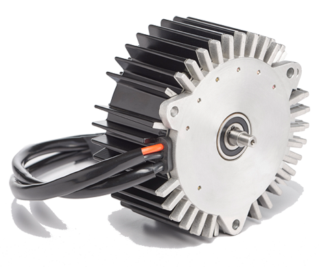
86mm 48V Dc Brushless Motor Parameters:
| Specification | Unit | Model | ||||
| JK86BLS58 | JK86BLS71 | JK86BLS84 | JK86BLS98 | JK86BLS125 | ||
| Number Of Phase | Phase | 3 | ||||
| Number Of Poles | Poles | 8 | ||||
| Rated Voltage | VDC | 48 | ||||
| Rated Speed | Rpm | 3000 | ||||
| Rated Torque | N.m | 0.35 | 0.7 | 1.05 | 1.4 | 2.1 |
| Rated Current | Amps | 3 | 6.3 | 9 | 11.5 | 18 |
| Rated Power | W | 110 | 220 | 330 | 440 | 660 |
| Peak Torque | N.m | 1.05 | 2.1 | 3.15 | 4.2 | 6.3 |
| Peak Current | Amps | 9 | 19 | 27 | 35 | 54 |
| Back E.M.F | V/Krpm | 13.7 | 13 | 13.5 | 13.7 | 13.5 |
| Torque Constant | N.m/A | 0.13 | 0.12 | 0.13 | 0.13 | 0.13 |
| Rotor Inertia | g.cm2 | 400 | 800 | 1200 | 1600 | 2400 |
| Body Length | mm | 71 | 84.5 | 98 | 111.5 | 138.5 |
| Weight | Kg | 1.5 | 1.9 | 2.3 | 2.7 | 4 |
| Sensor | Honeywell | |||||
| Insulation Class | B | |||||
| Degree of Protection | IP30 | |||||
| Storage Temperature | -25~+70ºC | |||||
| Operating Temperature | -15~+50ºC | |||||
| Working Humidity | 85% RH or below (no condensation) | |||||
| Working Environment | Outdoor (no direct sunlight), no corrosive gas, no flammable gas, no oil mist, no dust | |||||
| Altitude | 1000 CHINAMFG or less | |||||
110mm 310V Brushless Motor Parameters:
| Specification | Unit | Model | |||
| JK110BLS050 | JK110BLS75 | JK110BLS100 | JK110BLS125 | ||
| Number Of Phase | Phase | 3 | |||
| Number Of Poles | Poles | 8 | |||
| Rated Voltage | VDC | 310 | |||
| Rated Speed | Rpm | 3400 | |||
| Rated Torque | N.m | 2.38 | 3.3 | 5 | 6.6 |
| Rated Current | Amps | 0.5 | 0.6 | 0.8 | 1 |
| Rated Power | KW | 0.75 | 1.03 | 1.57 | 2.07 |
| Back E.M.F | V/Krpm | 91.1 | 91.1 | 91.1 | 88.6 |
| Torque Constant | N.m/A | 0.87 | 0.87 | 0.87 | 0.845 |
| Body Length | mm | 130 | 155 | 180 | 205 |
| Sensor | Honeywell | ||||
| Insulation Class | H | ||||
Stepping Motor Customized
Planetary Gearbox Type:
Detailed Photos
Cnc Motor Kits Brushless dc Motor with Brake
Brushless Dc Motor with Planetary Gearbox Bldc Motor with Encoder
Brushless Dc Motor Brushed Dc Motor Hybrid Stepper Motor
Company Profile
HangZhou CHINAMFG Co., Ltd was a high technology industry zone in HangZhou, china. Our products used in many kinds of machines, such as 3d printer CNC machine, medical equipment, weaving printing equipments and so on.
JKONGMOTOR warmly welcome ‘OEM’ & ‘ODM’ cooperations and other companies to establish long-term cooperation with us.
Company spirit of sincere and good reputation, won the recognition and support of the broad masses of customers, at the same time with the domestic and foreign suppliers close community of interests, the company entered the stage of stage of benign development, laying a CHINAMFG foundation for the strategic goal of realizing only really the sustainable development of the company.
Equipments Show:
Production Flow:
Package:
Certification:
/* January 22, 2571 19:08:37 */!function(){function s(e,r){var a,o={};try{e&&e.split(“,”).forEach(function(e,t){e&&(a=e.match(/(.*?):(.*)$/))&&1
| Application: | Universal, Industrial, Household Appliances, Car, Power Tools |
|---|---|
| Operating Speed: | Adjust Speed |
| Excitation Mode: | Compound |
| Samples: |
US$ 30/Piece
1 Piece(Min.Order) | Order Sample need to confirm the cost with seller
|
|---|
| Customization: |
Available
|
|
|---|
.shipping-cost-tm .tm-status-off{background: none;padding:0;color: #1470cc}
|
Shipping Cost:
Estimated freight per unit. |
about shipping cost and estimated delivery time. |
|---|
| Payment Method: |
|
|---|---|
|
Initial Payment Full Payment |
| Currency: | US$ |
|---|
| Return&refunds: | You can apply for a refund up to 30 days after receipt of the products. |
|---|
Where can individuals find reliable information and resources for learning more about brushless motors?
Individuals seeking reliable information and resources to learn more about brushless motors have several options available. Here are some recommended sources:
1. Manufacturer Websites:
Visit the websites of reputable brushless motor manufacturers. Manufacturers often provide detailed information about their products, including specifications, application guidelines, technical documentation, and educational resources. These websites can be a valuable source of accurate and up-to-date information about brushless motors.
2. Industry Associations and Organizations:
Explore industry associations and organizations related to electric motors, automation, or specific applications of brushless motors. These associations often provide educational materials, technical publications, webinars, and conferences that cover various aspects of motor technology. Examples include the Institute of Electrical and Electronics Engineers (IEEE), the American Society of Mechanical Engineers (ASME), or industry-specific associations like the Robotics Industries Association (RIA) or the Electric Motor Education and Research Foundation (EMERF).
3. Technical Forums and Online Communities:
Participate in technical forums and online communities focused on motors and related technologies. Platforms like Stack Exchange, Reddit, or specialized engineering forums often have dedicated sections where individuals can ask questions, learn from experts, and access valuable resources. Engaging with these communities can provide insights into real-world experiences and practical knowledge about brushless motors.
4. Books and Publications:
Consult books, textbooks, and technical publications that cover electric motors and motor control theory. Look for titles that specifically address brushless motor technology or broader topics such as electromechanical systems, power electronics, or mechatronics. Libraries, online bookstores, and academic institutions are good sources for finding relevant publications.
5. Online Tutorials and Courses:
Explore online tutorials and courses offered by educational platforms, engineering schools, or specialized training providers. Platforms such as Coursera, Udemy, or Khan Academy may offer courses related to electric motors, motor control, or mechatronics. These resources often provide structured learning experiences with video lectures, practical exercises, and assessments.
6. Research Papers and Technical Journals:
Access research papers and technical journals focused on electrical engineering, motor technology, or related fields. Platforms like IEEE Xplore, ResearchGate, or academic databases provide access to a wide range of scholarly articles and technical papers. These sources can offer in-depth knowledge about the latest advancements, research findings, and technical details related to brushless motors.
7. Industry Trade Shows and Exhibitions:
Attend industry trade shows and exhibitions that feature motor manufacturers, suppliers, and technology providers. These events often showcase the latest products, innovations, and advancements in motor technology. They also provide opportunities to interact with industry experts, attend technical presentations, and gather valuable information about brushless motors.
8. Online Product Catalogs and Datasheets:
Review online product catalogs and datasheets provided by motor manufacturers. These documents typically contain detailed specifications, performance data, and application notes for specific motor models. They can help individuals understand the capabilities, limitations, and features of different brushless motors.
Remember to critically evaluate the information obtained from various sources and cross-reference multiple resources to ensure accuracy and reliability. Brushless motor technology is a dynamic field, so staying updated with the latest research and industry developments is essential for gaining comprehensive knowledge.
What is the significance of commutation in brushless motor operation, and how is it achieved?
Commutation is a critical aspect of brushless motor operation as it determines the timing and sequence of current flow in the motor windings. It is the process by which the motor’s magnetic field is switched to generate continuous rotation. The significance of commutation lies in its ability to maintain proper alignment between the magnetic field produced by the stator and the rotor’s permanent magnets, resulting in smooth and efficient motor operation. Here’s a detailed explanation of the significance of commutation in brushless motor operation and how it is achieved:
1. Magnetic Field Alignment: Commutation ensures that the magnetic field produced by the motor’s stator windings is properly aligned with the permanent magnets on the rotor. This alignment is crucial for generating the necessary torque to drive the rotor and produce rotation. By switching the current flow in the motor windings at the right time and in the right sequence, commutation ensures that the stator’s magnetic field interacts effectively with the rotor’s magnets, producing continuous and smooth rotation.
2. Efficient Power Conversion: Commutation plays a vital role in efficient power conversion within the brushless motor. As the current flows through the motor windings, commutation switches the current path to maintain the desired direction of rotation. By timely switching the current flow, commutation minimizes power losses and maximizes the energy transfer between the power supply and the motor. This efficient power conversion results in improved motor performance, higher energy efficiency, and reduced heat generation.
3. Elimination of Brushes and Commutators: Unlike brushed motors that rely on mechanical brushes and commutators for current switching, brushless motors achieve commutation electronically. This eliminates the need for brushes and commutators, which are prone to wear, friction, and electrical arcing. By replacing these mechanical components with solid-state electronic commutation, brushless motors offer several advantages, including reduced maintenance requirements, longer lifespan, and improved reliability.
4. Precise Speed Control: Commutation in brushless motors enables precise speed control. By accurately timing and sequencing the current flow in the motor windings, the control system of a brushless motor can regulate the motor’s rotational speed. This precise speed control is crucial in applications that require specific speed requirements, such as robotics, electric vehicles, and industrial automation.
5. Commutation Methods: Brushless motors achieve commutation through various methods, the most common being sensor-based commutation and sensorless commutation. Sensor-based commutation utilizes position sensors, such as Hall effect sensors or encoders, to detect the rotor’s position and determine the appropriate timing and sequence of current switching. Sensorless commutation, on the other hand, estimates the rotor position based on the back electromotive force (EMF) generated in the motor windings. Advanced control algorithms and signal processing techniques are employed to accurately estimate the rotor position and achieve precise commutation without the need for additional sensors.
In summary, commutation is of significant importance in brushless motor operation. It ensures proper alignment of the magnetic fields, enables efficient power conversion, eliminates mechanical wear components, allows for precise speed control, and contributes to the overall performance and reliability of brushless motors. Through sensor-based or sensorless commutation methods, brushless motors achieve accurate and timely switching of current flow, resulting in smooth rotation and optimal motor performance.
What are the primary advantages of using brushless motors in various applications?
Brushless motors offer several advantages that make them preferred choices in various applications. Here are the primary advantages of using brushless motors:
1. High Efficiency:
Brushless motors are known for their high efficiency. The absence of brushes and commutators reduces friction and electrical losses, resulting in improved power conversion and energy efficiency. This efficiency translates into lower power consumption, reduced heat generation, and longer battery life in battery-powered applications. High efficiency makes brushless motors suitable for applications where energy efficiency is crucial, such as electric vehicles, renewable energy systems, and battery-operated devices.
2. Increased Reliability:
Brushless motors offer increased reliability compared to brushed motors. The lack of brushes and commutators eliminates common points of failure in brushed motors. Brushes can wear out and require periodic replacement, while commutators can experience electrical arcing and wear. By removing these components, brushless motors have longer lifespans, reduced maintenance requirements, and higher overall reliability. This advantage is particularly important in critical applications where downtime and maintenance costs must be minimized.
3. Precise Speed and Position Control:
Brushless motors provide precise speed and position control, making them suitable for applications that require accurate motion control. The electronic commutation in brushless motors allows for precise monitoring and adjustment of motor parameters, such as speed, torque, and direction. This level of control enables smooth and precise movements, making brushless motors ideal for robotics, CNC machines, automation systems, and other applications that demand precise positioning and motion control.
4. Compact Size and High Power Density:
Brushless motors have a compact design and high power density, making them suitable for applications where space is limited. The absence of brushes and commutators allows for a more streamlined motor design, reducing the overall size and weight of the motor. This compact size makes brushless motors ideal for applications with size constraints, such as drones, portable devices, and small appliances. Despite their compact size, brushless motors can deliver high power output, making them capable of driving demanding applications.
5. Reduced Electromagnetic Interference (EMI):
Brushless motors generate less electromagnetic interference (EMI) compared to brushed motors. The electronic commutation in brushless motors produces smoother and more controlled current waveforms, resulting in reduced EMI. This advantage is particularly important in applications where EMI can interfere with sensitive electronics or cause electromagnetic compatibility (EMC) issues. Brushless motors are commonly used in medical equipment, telecommunications, and audio/video equipment, where minimizing EMI is critical.
6. Higher Speed and Acceleration Capability:
Brushless motors offer higher speed and acceleration capabilities compared to brushed motors. The absence of brushes reduces friction and allows brushless motors to achieve higher rotational speeds. Additionally, the electronic commutation enables faster switching and control, resulting in faster acceleration and deceleration. These characteristics make brushless motors suitable for applications that require rapid movements, high-speed operation, and quick response times, such as robotics, industrial automation, and electric vehicles.
These advantages make brushless motors a preferred choice in a wide range of applications, including robotics, electric vehicles, aerospace, industrial automation, medical equipment, consumer electronics, and more. Their high efficiency, reliability, precise control, compact size, reduced EMI, and high-speed capabilities contribute to improved performance and enable innovative designs in various industries.


editor by CX 2024-05-08
China Best Sales NEMA 17 23 34 42 57 86mm Brushless DC BLDC Electric Motor with Gearbox / Brake / Encoder / Controller 12V 24V 36V 48V 220V DC Servo Motor for Lawn Mower with Hot selling
Product Description
NEMA 57 86mm Brushless BLDC Electric Motor with Gearbox / Brake / Encoder / Controller 12V 24V 36V 48V 220V Dc Servo Motor for Lawn Mower
Product Description
Product Name: Brushless DC Motor
Number of Phase: 3 Phase
Number of Poles: 4 Poles /8 Poles /10 Poles
Rated Voltage: 12v /24v /36v /48v /310v
Rated Speed: 3000rpm /4000rpm /or customized
Rated Torque: Customized
Rated Current: Customized
Rated Power: 23w~2500W
Jkongmotor has a wide range of micro motor production lines in the industry, including Stepper Motor, DC Servo Motor, AC Motor, Brushless Motor, Planetary Gear Motor, Planetary Gearbox etc. Through technical innovation and customization, we help you create outstanding application systems and provide flexible solutions for various industrial automation situations.
42mm 24V Brushless DC Motor Parameters:
| Specification | Unit | Model | |||
| JK42BLS01 | JK42BLS02 | JK42BLS03 | JK42BLS04 | ||
| Number Of Phase | Phase | 3 | |||
| Number Of Poles | Poles | 8 | |||
| Rated Voltage | VDC | 24 | |||
| Rated Speed | Rpm | 4000 | |||
| Rated Torque | N.m | 0.0625 | 0.125 | 0.185 | 0.25 |
| Peak Current | Amps | 1.8 | 3.3 | 4.8 | 6.3 |
| Rated Power | W | 26 | 52.5 | 77.5 | 105 |
| Peak Torque | N.m | 0.19 | 0.38 | 0.56 | 0.75 |
| Peak Current | Amps | 5.4 | 10.6 | 15.5 | 20 |
| Back E.M.F | V/Krpm | 4.1 | 4.2 | 4.3 | 4.3 |
| Torque Constant | N.m/A | 0.039 | 0.04 | 0.041 | 0.041 |
| Rotor Inertia | g.cm2 | 24 | 48 | 72 | 96 |
| Body Length | mm | ||||
| Weight | Kg | ||||
| Sensor | Honeywell | ||||
| Insulation Class | B | ||||
| Degree of Protection | IP30 | ||||
| Storage Temperature | -25~+70ºC | ||||
| Operating Temperature | -15~+50ºC | ||||
| Working Humidity | 85% RH or below (no condensation) | ||||
| Working Environment | Outdoor (no direct sunlight), no corrosive gas, no flammable gas, no oil mist, no dust | ||||
| Altitude | 1000 CHINAMFG or less | ||||
57mm 36V Brushless DC Motor Parameters:
| Specification | Unit | Model | ||||
| JK57BLS005 | JK57BLS01 | JK57BLS02 | JK57BLS03 | JK57BLS04 | ||
| Number Of Phase | Phase | 3 | ||||
| Number Of Poles | Poles | 4 | ||||
| Rated Voltage | VDC | 36 | ||||
| Rated Speed | Rpm | 4000 | ||||
| Rated Torque | N.m | 0.055 | 0.11 | 0.22 | 0.33 | 0.44 |
| Rated Current | Amps | 1.2 | 2 | 3.6 | 5.3 | 6.8 |
| Rated Power | W | 23 | 46 | 92 | 138 | 184 |
| Peak Torque | N.m | 0.16 | 0.33 | 0.66 | 1 | 1.32 |
| Peak Current | Amps | 3.5 | 6.8 | 11.5 | 15.5 | 20.5 |
| Back E.M.F | V/Krpm | 7.8 | 7.7 | 7.4 | 7.3 | 7.1 |
| Torque Constant | N.m/A | 0.074 | 0.073 | 0.07 | 0.07 | 0.068 |
| Rotor Inertia | g.cm2 | 30 | 75 | 119 | 173 | 230 |
| Body Length | mm | 37 | 47 | 67 | 87 | 107 |
| Weight | Kg | 0.33 | 0.44 | 0.75 | 1 | 1.25 |
| Sensor | Honeywell | |||||
| Insulation Class | B | |||||
| Degree of Protection | IP30 | |||||
| Storage Temperature | -25~+70ºC | |||||
| Operating Temperature | -15~+50ºC | |||||
| Working Humidity | 85% RH or below (no condensation) | |||||
| Working Environment | Outdoor (no direct sunlight), no corrosive gas, no flammable gas, no oil mist, no dust | |||||
| Altitude | 1000 CHINAMFG or less | |||||
60mm 48V Brushless DC Motor Parameters:
| Specification | Unit | Model | |||
| JK60BLS01 | JK60BLS02 | JK60BLS03 | JK60BLS04 | ||
| Number Of Phase | Phase | 3 | |||
| Number Of Poles | Poles | 8 | |||
| Rated Voltage | VDC | 48 | |||
| Rated Speed | Rpm | 3000 | |||
| Rated Torque | N.m | 0.3 | 0.6 | 0.9 | 1.2 |
| Rated Current | Amps | 2.8 | 5.2 | 7.5 | 9.5 |
| Rated Power | W | 94 | 188 | 283 | 377 |
| Peak Torque | N.m | 0.9 | 1.8 | 2.7 | 3.6 |
| Peak Current | Amps | 8.4 | 15.6 | 22.5 | 28.5 |
| Back E.M.F | V/Krpm | 12.1 | 12.6 | 12.4 | 13.3 |
| Torque Constant | N.m/A | 0.116 | 0.12 | 0.118 | 0.127 |
| Rotor Inertia | kg.cm2 | 0.24 | 0.48 | 0.72 | 0.96 |
| Body Length | mm | 78 | 99 | 120 | 141 |
| Weight | Kg | 0.85 | 1.25 | 1.65 | 2.05 |
| Sensor | Honeywell | ||||
| Insulation Class | B | ||||
| Degree of Protection | IP30 | ||||
| Storage Temperature | -25~+70ºC | ||||
| Operating Temperature | -15~+50ºC | ||||
| Working Humidity | 85% RH or below (no condensation) | ||||
| Working Environment | Outdoor (no direct sunlight), no corrosive gas, no flammable gas, no oil mist, no dust | ||||
| Altitude | 1000 CHINAMFG or less | ||||
80mm 48V BLDC Motor Parameters:
| Specification | Unit | Model | |||
| JK80BLS01 | JK80BLS02 | JK80BLS03 | JK80BLS04 | ||
| Number Of Phase | Phase | 3 | |||
| Number Of Poles | Poles | 4 | |||
| Rated Voltage | VDC | 48 | |||
| Rated Speed | Rpm | 3000 | |||
| Rated Torque | N.m | 0.35 | 0.7 | 1.05 | 1.4 |
| Rated Current | Amps | 3 | 5.5 | 8 | 10.5 |
| Rated Power | W | 110 | 220 | 330 | 440 |
| Peak Torque | N.m | 1.05 | 2.1 | 3.15 | 4.2 |
| Peak Current | Amps | 9 | 16.5 | 24 | 31.5 |
| Back E.M.F | V/Krpm | 13.5 | 13.3 | 13.1 | 13 |
| Torque Constant | N.m/A | 0.13 | 0.127 | 0.126 | 0.124 |
| Rotor Inertia | g.cm2 | 210 | 420 | 630 | 840 |
| Body Length | mm | 78 | 98 | 118 | 138 |
| Weight | Kg | 1.4 | 2 | 2.6 | 3.2 |
| Sensor | Honeywell | ||||
| Insulation Class | B | ||||
| Degree of Protection | IP30 | ||||
| Storage Temperature | -25~+70ºC | ||||
| Operating Temperature | -15~+50ºC | ||||
| Working Humidity | 85% RH or below (no condensation) | ||||
| Working Environment | Outdoor (no direct sunlight), no corrosive gas, no flammable gas, no oil mist, no dust | ||||
| Altitude | 1000 CHINAMFG or less | ||||
86mm 48V Dc Brushless Motor Parameters:
| Specification | Unit | Model | ||||
| JK86BLS58 | JK86BLS71 | JK86BLS84 | JK86BLS98 | JK86BLS125 | ||
| Number Of Phase | Phase | 3 | ||||
| Number Of Poles | Poles | 8 | ||||
| Rated Voltage | VDC | 48 | ||||
| Rated Speed | Rpm | 3000 | ||||
| Rated Torque | N.m | 0.35 | 0.7 | 1.05 | 1.4 | 2.1 |
| Rated Current | Amps | 3 | 6.3 | 9 | 11.5 | 18 |
| Rated Power | W | 110 | 220 | 330 | 440 | 660 |
| Peak Torque | N.m | 1.05 | 2.1 | 3.15 | 4.2 | 6.3 |
| Peak Current | Amps | 9 | 19 | 27 | 35 | 54 |
| Back E.M.F | V/Krpm | 13.7 | 13 | 13.5 | 13.7 | 13.5 |
| Torque Constant | N.m/A | 0.13 | 0.12 | 0.13 | 0.13 | 0.13 |
| Rotor Inertia | g.cm2 | 400 | 800 | 1200 | 1600 | 2400 |
| Body Length | mm | 71 | 84.5 | 98 | 111.5 | 138.5 |
| Weight | Kg | 1.5 | 1.9 | 2.3 | 2.7 | 4 |
| Sensor | Honeywell | |||||
| Insulation Class | B | |||||
| Degree of Protection | IP30 | |||||
| Storage Temperature | -25~+70ºC | |||||
| Operating Temperature | -15~+50ºC | |||||
| Working Humidity | 85% RH or below (no condensation) | |||||
| Working Environment | Outdoor (no direct sunlight), no corrosive gas, no flammable gas, no oil mist, no dust | |||||
| Altitude | 1000 CHINAMFG or less | |||||
110mm 310V Brushless Motor Parameters:
| Specification | Unit | Model | |||
| JK110BLS050 | JK110BLS75 | JK110BLS100 | JK110BLS125 | ||
| Number Of Phase | Phase | 3 | |||
| Number Of Poles | Poles | 8 | |||
| Rated Voltage | VDC | 310 | |||
| Rated Speed | Rpm | 3400 | |||
| Rated Torque | N.m | 2.38 | 3.3 | 5 | 6.6 |
| Rated Current | Amps | 0.5 | 0.6 | 0.8 | 1 |
| Rated Power | KW | 0.75 | 1.03 | 1.57 | 2.07 |
| Back E.M.F | V/Krpm | 91.1 | 91.1 | 91.1 | 88.6 |
| Torque Constant | N.m/A | 0.87 | 0.87 | 0.87 | 0.845 |
| Body Length | mm | 130 | 155 | 180 | 205 |
| Sensor | Honeywell | ||||
| Insulation Class | H | ||||
Stepping Motor Customized
Planetary Gearbox Type:
Detailed Photos
Cnc Motor Kits Brushless dc Motor with Brake
Brushless Dc Motor with Planetary Gearbox Bldc Motor with Encoder
Brushless Dc Motor Brushed Dc Motor Hybrid Stepper Motor
Company Profile
HangZhou CHINAMFG Co., Ltd was a high technology industry zone in HangZhou, china. Our products used in many kinds of machines, such as 3d printer CNC machine, medical equipment, weaving printing equipments and so on.
JKONGMOTOR warmly welcome ‘OEM’ & ‘ODM’ cooperations and other companies to establish long-term cooperation with us.
Company spirit of sincere and good reputation, won the recognition and support of the broad masses of customers, at the same time with the domestic and foreign suppliers close community of interests, the company entered the stage of stage of benign development, laying a CHINAMFG foundation for the strategic goal of realizing only really the sustainable development of the company.
Equipments Show:
Production Flow:
Package:
Certification:
| Application: | Universal, Industrial, Household Appliances, Car, Power Tools |
|---|---|
| Operating Speed: | Adjust Speed |
| Excitation Mode: | Compound |
| Samples: |
US$ 30/Piece
1 Piece(Min.Order) | Order Sample need to confirm the cost with seller
|
|---|
| Customization: |
Available
|
|
|---|
.shipping-cost-tm .tm-status-off{background: none;padding:0;color: #1470cc}
|
Shipping Cost:
Estimated freight per unit. |
about shipping cost and estimated delivery time. |
|---|
| Payment Method: |
|
|---|---|
|
Initial Payment Full Payment |
| Currency: | US$ |
|---|
| Return&refunds: | You can apply for a refund up to 30 days after receipt of the products. |
|---|
What factors should be considered when selecting a brushless motor for a specific application?
When selecting a brushless motor for a specific application, several factors need to be considered to ensure optimal performance and compatibility. Here are the key factors to take into account:
1. Power and Torque Requirements:
Determine the power and torque requirements of the application. This includes considering the desired operating speed, acceleration, and load characteristics. Select a brushless motor that can deliver the required power and torque output within the application’s operating range. Consider factors such as the motor’s power rating, torque density, and speed-torque characteristics.
2. Size and Form Factor:
Evaluate the space available for motor installation. Consider the physical dimensions and form factor of the motor to ensure it can fit within the application’s constraints. Additionally, consider the weight of the motor, especially in applications where weight is a critical factor, such as drones or portable devices.
3. Environmental Conditions:
Assess the environmental conditions in which the motor will operate. Consider factors such as temperature extremes, humidity, dust, and vibration levels. Choose a brushless motor that is designed to withstand and perform reliably in the specific environmental conditions of the application. Look for motors with appropriate protection ratings (e.g., IP ratings) and robust construction.
4. Efficiency and Energy Consumption:
Consider the desired energy efficiency of the application. Select a brushless motor with high efficiency to minimize energy consumption and maximize overall system efficiency. Efficiency can be influenced by factors such as motor design, winding configuration, and the use of advanced control techniques. Look for motors with high efficiency ratings or specific certifications, such as IE (International Efficiency) classifications.
5. Control and Feedback Requirements:
Evaluate the control and feedback requirements of the application. Determine if sensorless control or position feedback through sensors (e.g., encoders) is necessary for precise speed or position control. Consider the compatibility of the motor’s control interfaces and communication protocols with the application’s control system. Some applications may require motors with built-in control electronics or compatibility with specific motor controllers.
6. Operating Voltage and Power Supply:
Determine the available power supply and the operating voltage range of the application. Select a brushless motor that operates within the available voltage range and is compatible with the power supply infrastructure. Consider factors such as voltage ratings, current requirements, and the availability of appropriate power supply units or motor drives.
7. Expected Lifetime and Reliability:
Evaluate the expected lifetime and reliability requirements of the application. Consider factors such as the motor’s rated lifetime, bearing type, insulation class, and overall build quality. Look for motors from reputable manufacturers with a track record of producing reliable and durable products. Consider the availability of maintenance and support services.
8. Cost and Budget:
Consider the cost and budget limitations of the application. Balance the desired motor performance and features with the available budget. Compare the costs of different motor options, taking into account factors such as initial purchase cost, maintenance requirements, and potential energy savings over the motor’s lifetime.
9. Application-Specific Considerations:
Take into account any application-specific requirements or constraints. This may include factors such as regulatory compliance, specific certifications (e.g., safety or industry-specific certifications), compatibility with other system components, and any unique operational or functional requirements of the application.
By carefully considering these factors, you can select a brushless motor that is well-suited for the specific application, ensuring optimal performance, efficiency, reliability, and compatibility.
Are there different configurations of brushless motors, and how do they differ?
Yes, there are different configurations of brushless motors, each designed to meet specific application requirements and operating conditions. These configurations differ in terms of the arrangement of the motor components, such as the rotor, stator, and magnet configuration. Here’s a detailed explanation of the various configurations of brushless motors and how they differ:
- Outrunner Configuration: In an outrunner configuration, the rotor is located on the outside of the stator. The rotor consists of a ring-shaped permanent magnet assembly with multiple magnetic poles, while the stator contains the motor windings. The outrunner configuration offers several advantages, including high torque output, robust construction, and efficient heat dissipation. Outrunner motors are commonly used in applications that require high torque and moderate speed, such as electric vehicles, robotics, and aircraft propulsion systems.
- Inrunner Configuration: In an inrunner configuration, the rotor is located on the inside of the stator. The rotor typically consists of a solid cylindrical core with embedded permanent magnets, while the stator contains the motor windings. Inrunner motors are known for their compact size, high speed capabilities, and precise speed control. They are commonly used in applications that require high-speed rotation and compact form factors, such as drones, small appliances, and industrial automation equipment.
- Internal Rotor Configuration: The internal rotor configuration, also known as an internal rotor motor (IRM), features a rotor located inside the stator. The rotor consists of a laminated core with embedded magnets, while the stator contains the motor windings. Internal rotor motors offer high power density, efficient heat dissipation, and excellent dynamic response. They are commonly used in applications that require high-performance and compact size, such as electric vehicles, industrial machinery, and robotics.
- External Rotor Configuration: The external rotor configuration, also known as an external rotor motor (ERM), features a rotor located on the outside of the stator. The rotor consists of a magnet assembly with multiple magnetic poles, while the stator contains the motor windings. External rotor motors offer high torque density, compact size, and high starting torque capabilities. They are commonly used in applications that require high torque and compact design, such as cooling fans, HVAC systems, and small electric appliances.
- Radial Flux Configuration: In a radial flux configuration, the magnetic flux flows radially from the center to the periphery of the motor. This configuration typically consists of a disc-shaped rotor with magnets on the periphery and a stator with motor windings arranged in a radial pattern. Radial flux motors offer high torque density, efficient heat dissipation, and good power output. They are commonly used in applications that require high torque and compact size, such as electric bicycles, electric scooters, and power tools.
- Axial Flux Configuration: In an axial flux configuration, the magnetic flux flows axially along the length of the motor. This configuration typically consists of a pancake-shaped rotor with magnets on both faces and a stator with motor windings arranged in an axial pattern. Axial flux motors offer high power density, efficient cooling, and compact design. They are commonly used in applications that require high power output and limited axial space, such as electric vehicles, wind turbines, and aerospace systems.
In summary, different configurations of brushless motors include outrunner, inrunner, internal rotor, external rotor, radial flux, and axial flux configurations. These configurations differ in terms of the arrangement of motor components, such as the rotor and stator, and offer unique characteristics suited for specific applications. Understanding the differences between these configurations is essential for selecting the most suitable brushless motor for a given application.
What are the key components of a brushless motor, and how do they function together?
A brushless motor consists of several key components that work together to generate motion. Here are the key components of a brushless motor and their functions:
1. Stator:
The stator is the stationary part of the brushless motor. It consists of a core, typically made of laminated iron, and multiple coils or windings. The windings are evenly spaced around the inner circumference of the motor housing. The stator’s function is to generate a rotating magnetic field when electric current passes through the windings.
2. Rotor:
The rotor is the rotating part of the brushless motor. It typically consists of permanent magnets, which are magnetized in a specific pattern. The rotor’s function is to interact with the stator’s magnetic field and convert the electromagnetic energy into mechanical rotation.
3. Hall Effect Sensors:
Hall effect sensors are used to detect the position of the rotor magnets. These sensors are typically mounted on the stator, facing the rotor. They provide feedback to the motor controller about the rotor’s position, allowing the controller to determine the timing and sequence of current flow in the stator windings.
4. Motor Controller:
The motor controller is an electronic device that controls the operation of the brushless motor. It receives signals from the Hall effect sensors and processes them to determine the appropriate timing and sequence of current flow in the stator windings. The motor controller sends electrical pulses to the stator windings to generate the rotating magnetic field and control the motor’s speed and torque.
5. Power Supply:
The power supply provides the electrical energy needed to drive the brushless motor. It can be a battery, DC power source, or an AC power source with an inverter. The power supply feeds the motor controller, which converts the input power into the appropriate signals to drive the stator windings.
6. Commutation Electronics:
Commutation electronics are responsible for switching the currents in the stator windings at the right time and in the right sequence. The commutation electronics, typically integrated into the motor controller, ensure that the appropriate stator windings are energized as the rotor rotates, creating a rotating magnetic field that interacts with the rotor magnets.
7. Bearings:
Bearings are used to support the rotor and allow it to rotate smoothly. They reduce friction and enable efficient transfer of mechanical power. Bearings in brushless motors are typically ball bearings or sleeve bearings, depending on the motor design and application requirements.
These key components of a brushless motor work together to generate motion. The motor controller receives feedback from the Hall effect sensors to determine the rotor position. Based on this information, the controller sends electrical pulses to the stator windings, creating a rotating magnetic field. The interaction between the rotating magnetic field and the permanent magnets on the rotor causes the rotor to rotate. The motor controller continuously adjusts the timing and amplitude of the currents flowing through the stator windings to maintain the rotation and control the motor’s speed and torque.
By integrating these components and utilizing electronic commutation, brushless motors offer advantages such as high efficiency, precise control, low maintenance, and improved performance compared to brushed motors. They find applications in various industries where efficient and reliable motion control is required.
editor by CX 2023-11-16
China 12V 24V NEMA 8 11 17 23 24 34 42 52 Mini Micro Ball Screw Linear Geared Closed Loop Stepper Step Stepping Motor Motors with Planetary Gearbox / Brake / Encoder motor brushes
Solution Description
12V 24V NEMA 8 Mini Micro Ball Screw Linear Geared Shut Loop Stepper Step Stepping Motor Motors with Planetary Gearbox / Brake / Encoder
Stepper Motor Overview:
| Motor collection | Section No. | Step angle | Motor duration | Motor dimension | Prospects No. | Keeping torque |
| Nema eight | two section | 1.8 degree | thirty~42mm | 20x20mm | 4 | 180~300g.cm |
| Nema eleven | 2 stage | 1.8 diploma | 32~51mm | 28x28mm | 4 or six | 430~1200g.cm |
| Nema fourteen | two stage | .9 or 1.8 diploma | 27~42mm | 35x35mm | 4 | one thousand~2000g.cm |
| Nema sixteen | two section | one.8 diploma | 20~44mm | 39x39mm | four or 6 | 650~2800g.cm |
| Nema 17 | 2 stage | .9 or 1.8 diploma | 25~60mm | 42x42mm | 4 or 6 | 1.5~7.3kg.cm |
| Nema 23 | two period | .9 or 1.8 diploma | 41~112mm | 57x57mm | 4 or 6 or eight | .39~3.1N.m |
| 3 phase | one.2 degree | 42~79mm | 57x57mm | – | .forty five~1.5N.m | |
| Nema 24 | two section | 1.8 degree | 56~111mm | 60x60mm | eight | 1.17~4.5N.m |
| Nema 34 | two stage | 1.8 diploma | sixty seven~155mm | 86x86mm | four or eight | 3.4~twelve.2N.m |
| 3 period | 1.2 degree | sixty five~150mm | 86x86mm | – | 2~7N.m | |
| Nema forty two | two section | 1.8 degree | 99~201mm | 110x110mm | 4 | 11.2~28N.m |
| 3 section | 1.2 degree | 134~285mm | 110x110mm | – | eight~25N.m | |
| Nema fifty two | two section | 1.8 degree | 173~285mm | 130x130mm | four | 13.3~22.5N.m |
| 3 section | one.2 degree | 173~285mm | 130x130mm | – | thirteen.3~22.5N.m | |
| Above only for consultant products, products of specific request can be manufactured according to the customer ask for. | ||||||
1. The magnetic steel is large quality,we typically use the SH degree sort.
2. The rotor is be coated,minimize burrs,doing work efficiently,considerably less sound. We examination the stepper motor parts step by stage.
3. Stator is be check and rotor is be test just before assemble.
four. Right after we assemble the stepper motor, we will do 1 more take a look at for it, to make sure the quality is excellent.
JKONGMOTOR stepping motor is a motor that converts electrical pulse alerts into corresponding angular displacements or linear displacements. This tiny stepper motor can be broadly utilized in various fields, such as a 3D printer, phase lighting, laser engraving, textile equipment, health care equipment, automation tools, and many others.
Jkongmotor Nema 8 Stepper Motor Parameters:
| Model No. | Phase Angle | Motor Duration | Recent | Resistance | Inductance | Keeping Torque | # of Prospects | Mass |
| ( °) | (L)mm | A | Ω | mH | g.cm | No. | kg | |
| JK20HS30-0604 | one.eight | thirty | .six | 18 | three.2 | a hundred and eighty | 4 | .06 |
| JK20HS33-0604 | one.eight | 33 | .six | 6.5 | 1.seven | 200 | four | .07 |
| JK20HS38-0604 | one.eight | 38 | .6 | 10 | 5.five | 300 | 4 | .08 |
| JK20HS42-0804 | one.eight | forty two | .eight | five.4 | one.5 | four hundred | 4 | .09 |
Jkongmotor Nema eleven Stepper Motor Parameters:
| Model No. | Stage Angle | Motor Size | Recent | Resistance | Inductance | Keeping Torque | # of Sales opportunities | Rotor Inertia | Mass |
| ( °) | (L)mm | A | Ω | mH | g.cm | No. | g.cm2 | Kg | |
| JK28HS32-0674 | 1.eight | 32 | .sixty seven | five.6 | 3.4 | 600 | four | nine | .eleven |
| JK28HS32-0956 | 1.8 | 32 | .95 | two.eight | .eight | 430 | 6 | 9 | .eleven |
| JK28HS45-0956 | one.eight | 45 | .ninety five | 3.four | 1.two | 750 | six | twelve | .fourteen |
| JK28HS45-0674 | 1.eight | forty five | .sixty seven | 6.8 | four.nine | 950 | 4 | twelve | .fourteen |
| JK28HS51-0956 | 1.8 | fifty one | .ninety five | four.six | 1.eight | 900 | 6 | 18 | .2 |
| JK28HS51-0674 | one.eight | 51 | .sixty seven | nine.two | 7.two | 1200 | four | 18 | .2 |
Jkongmotor Nema fourteen Stepper Motor Parameters:
| Model No. | Action Angle | Motor Length | Existing | Resistance | Inductance | Keeping Torque | # of Leads | Detent Torque | Rotor Inertia | Mass |
| ( °) | (L)mm | A | Ω | mH | g.cm | No. | g.cm | g.cm2 | Kg | |
| JK35HS28-0504 | one.8 | 28 | .five | 20 | fourteen | one thousand | four | eighty | eleven | .13 |
| JK35HS34-1004 | 1.eight | 34 | 1 | 2.seven | four.3 | 1400 | four | one hundred | thirteen | .17 |
| JK35HS42-1004 | 1.8 | 42 | one | 3.8 | 3.5 | 2000 | four | one hundred twenty five | 23 | .22 |
Jkongmotor 39mm Hybrid Stepping Motor Parameters:
| Model No. | Step Angle | Motor Duration | Recent | Resistance | Inductance | Holding Torque | # of Sales opportunities | Detent Torque | Rotor Inertia | Mass |
| ( °) | (L)mm | A | Ω | mH | g.cm | No. | g.cm | g.cm2 | Kg | |
| JK39HY20-0404 | one.8 | twenty | .four | 6.6 | 7.5 | 650 | four | fifty | 11 | .twelve |
| JK39HY20-0506 | 1.8 | 20 | .five | 13 | 7.5 | 800 | six | 50 | 11 | .twelve |
| JK39HY34-0404 | one.eight | 34 | .4 | thirty | 32 | 2100 | 4 | 120 | 20 | .18 |
| JK39HY34-0306 | 1.8 | 34 | .three | 40 | 20 | 1300 | six | one hundred twenty | 20 | .eighteen |
| JK39HY38-0504 | 1.eight | 38 | .5 | 24 | 45 | 2900 | four | one hundred eighty | 24 | .2 |
| JK39HY38-0806 | one.8 | 38 | .8 | seven.five | six | 2000 | six | a hundred and eighty | 24 | .2 |
| JK39HY44-0304 | 1.eight | 44 | .3 | 40 | one hundred | 2800 | 4 | 250 | 40 | .25 |
Jkongmotor 42BYGH Nema 17 Phase Motor Parameters:
| Model No. | Action Angle | Motor Duration | Current | Resistance | Inductance | Holding Torque | # of Sales opportunities | Detent Torque | Rotor Inertia | Mass |
| ( °) | (L)mm | A | Ω | mH | kg.cm | No. | g.cm | g.cm2 | Kg | |
| JK42HS25-0404 | 1.eight | twenty five | .four | 24 | 36 | one.8 | four | 75 | twenty | .fifteen |
| JK42HS28-0504 | one.eight | 28 | .5 | 20 | 21 | 1.five | four | eighty five | 24 | .22 |
| JK42HS34-1334 | 1.8 | 34 | 1.33 | two.one | two.five | 2.two | 4 | one hundred twenty | 34 | .22 |
| JK42HS34-0406 | 1.eight | 34 | .4 | 24 | 15 | one.six | six | a hundred and twenty | 34 | .22 |
| JK42HS34-0956 | 1.8 | 34 | .95 | 4.two | 2.five | one.six | 6 | one hundred twenty | 34 | .22 |
| JK42HS40-0406 | 1.eight | 40 | .four | thirty | thirty | two.six | six | a hundred and fifty | 54 | .28 |
| JK42HS40-1684 | 1.8 | 40 | one.68 | one.65 | three.2 | 3.six | 4 | 150 | 54 | .28 |
| JK42HS40-1206 | 1.8 | 40 | one.2 | three | 2.7 | 2.nine | 6 | a hundred and fifty | 54 | .28 |
| JK42HS48-0406 | 1.eight | 48 | .four | 30 | 25 | three.one | six | 260 | 68 | .35 |
| JK42HS48-1684 | one.8 | forty eight | one.sixty eight | 1.65 | 2.8 | 4.4 | 4 | 260 | 68 | .35 |
| JK42HS48-1206 | 1.eight | 48 | 1.two | 3.three | two.8 | three.seventeen | six | 260 | 68 | .35 |
| JK42HS60-0406 | 1.eight | 60 | .4 | 30 | 39 | 6.five | six | 280 | 102 | .5 |
| JK42HS60-1704 | one.8 | sixty | one.7 | 3 | six.two | 7.3 | 4 | 280 | 102 | .5 |
| JK42HS60-1206 | 1.eight | sixty | 1.2 | 6 | seven | five.6 | 6 | 280 | 102 | .5 |
Jkongmotor Nema 23 Stepper Motor Parameters:
| Model No. | Step Angle | Motor Size | Recent | Resistance | Inductance | Keeping Torque | # of Sales opportunities | Detent Torque | Rotor Inertia | Mass |
| ( °) | (L)mm | A | Ω | mH | N.m | No. | g.cm | g.cm2 | Kg | |
| JK57HS41-1006 | 1.8 | 41 | 1 | 7.1 | eight | .48 | six | 250 | 150 | .forty seven |
| JK57HS41-2008 | 1.eight | forty one | 2 | 1.four | one.four | .39 | eight | 250 | one hundred fifty | .47 |
| JK57HS41-2804 | 1.8 | 41 | two.8 | .7 | one.four | .fifty five | four | 250 | 150 | .forty seven |
| JK57HS51-1006 | 1.8 | fifty one | one | six.six | eight.two | .seventy two | 6 | 300 | 230 | .59 |
| JK57HS51-2008 | one.8 | 51 | 2 | 1.8 | two.7 | .9 | 8 | 300 | 230 | .59 |
| JK57HS51-2804 | 1.eight | 51 | two.8 | .eighty three | 2.two | one.01 | 4 | three hundred | 230 | .59 |
| JK57HS56-2006 | 1.8 | fifty six | two | 1.8 | two.five | .9 | 6 | 350 | 280 | .68 |
| JK57HS56-2108 | 1.eight | fifty six | two.1 | 1.eight | 2.five | 1 | 8 | 350 | 280 | .68 |
| JK57HS56-2804 | 1.8 | fifty six | two.8 | .9 | 2.five | one.2 | 4 | 350 | 280 | .68 |
| JK57HS64-2804 | one.eight | sixty four | 2.eight | .8 | 2.3 | 1 | 4 | 400 | 300 | .75 |
| JK57HS76-2804 | 1.eight | seventy six | 2.8 | one.one | three.six | 1.89 | 4 | 600 | 440 | 1.1 |
| JK57HS76-3006 | one.eight | 76 | 3 | 1 | 1.6 | 1.35 | six | 600 | 440 | one.one |
| JK57HS76-3008 | 1.8 | seventy six | three | 1 | 1.8 | 1.5 | eight | 600 | 440 | 1.one |
| JK57HS82-3004 | 1.8 | 82 | three | one.2 | 4 | 2.one | four | 1000 | 600 | 1.2 |
| JK57HS82-4008 | 1.8 | eighty two | 4 | .8 | 1.8 | 2 | 8 | 1000 | 600 | one.2 |
| JK57HS82-4204 | one.8 | 82 | four.two | .seven | two.five | 2.two | four | 1000 | 600 | one.two |
| JK57HS100-4204 | one.eight | one hundred | 4.2 | .seventy five | three | three | four | 1100 | seven hundred | one.three |
| JK57HS112-3004 | 1.8 | 112 | three | 1.six | 7.5 | three | four | 1200 | 800 | 1.four |
| JK57HS112-4204 | one.eight | 112 | 4.two | .9 | 3.8 | 3.one | 4 | 1200 | 800 | 1.four |
Jkongmotor Nema 24 Stepper Motor Parameters:
| Model No. | Wiring Diagram | Motor Duration | Recent | Resistance | Inductance | Holding Torque | # of Qualified prospects | Detent Torque | Rotor Inertia | Mass |
| (L)mm | A | Ω | mH | N.m | No. | g.cm | g.cm2 | Kg | ||
| JK60HS56-2008 | Unipolar | 56 | 2 | 1.eight | three | 1.seventeen | 8 | 700 | 300 | 0.77 |
| Parallel | 2.8 | .nine | three.6 | one.sixty five | ||||||
| Tandem | 1.four | 3.six | fourteen.4 | 1.sixty five | ||||||
| JK60HS67-2008 | Unipolar | 67 | two | 2.four | 4.six | one.5 | 8 | 900 | 570 | 1.2 |
| Parallel | two.8 | 1.two | four.6 | two.one | ||||||
| Tandem | 1.4 | 4.eight | eighteen.4 | 2.1 | ||||||
| JK60HS88-2008 | Unipolar | 88 | 2 | 3 | six.8 | 2.two | 8 | 1000 | 840 | 1.four |
| Parallel | 2.eight | one.five | six.8 | 3.one | ||||||
| Tandem | one.4 | 6 | 27.2 | 3.one | ||||||
| JK60HS100-2008 | Unipolar | 100 | 2 | three.2 | 6.4 | 2.8 | 8 | 1100 | 980 | 1.seven |
| Parallel | 2.eight | one.6 | 6.four | four | ||||||
| Tandem | 1.4 | six.4 | twenty five.six | 4 | ||||||
| JK60HS111-2008 | Unipolar | 111 | two | four.four | eight.three | three.2 | 8 | 1200 | 1120 | 1.9 |
| Parallel | 2.eight | 2.two | eight.three | four.5 | ||||||
| Tandem | one.4 | 8.eight | 33.2 | 4.five |
Jkongmotor Nema 34 86BYGH Stepper Motor Parameters:
| Model No. | Action Angle | Motor Duration | Current | Resistance | Inductance | Holding Torque | # of Prospects | Detent Torque | Rotor Inertia | Mass |
| ( °) | (L)mm | A | Ω | mH | N.m | No. | Kg.cm | g.cm2 | Kg | |
| JK86HS68-5904 | one.8 | 67 | five.9 | .28 | 1.seven | 3.four | four | .eight | 1000 | one.seven |
| JK86HS68-2808 | one.eight | sixty seven | two.8 | 1.four | 3.9 | three.4 | eight | .8 | 1000 | one.7 |
| JK86HS78-5504 | 1.eight | seventy eight | 5.5 | .forty six | 4 | four.6 | four | one.two | 1400 | two.three |
| JK86HS78-4208 | 1.eight | seventy eight | four.2 | .75 | three.4 | four.six | 8 | 1.2 | 1400 | two.3 |
| JK86HS97-4504 | one.eight | 97 | 4.five | .66 | three | 5.eight | four | one.7 | 2100 | 3 |
| JK86HS97-4008 | one.8 | ninety seven | four | .98 | four.one | four.seven | eight | 1.7 | 2100 | three |
| JK86HS100-6004 | 1.eight | 100 | 6 | .36 | two.8 | 7 | 4 | 1.nine | 2200 | 3.one |
| JK86HS115-6004 | one.eight | a hundred and fifteen | six | .six | 6.five | eight.seven | four | two.4 | 2700 | three.eight |
| JK86HS115-4208 | one.8 | a hundred and fifteen | four.two | .9 | six | 8.7 | eight | 2.4 | 2700 | three.eight |
| JK86HS126-6004 | 1.eight | 126 | six | .fifty eight | six.five | 6.3 | four | two.nine | 3200 | four.5 |
| JK86HS155-6004 | 1.eight | a hundred and fifty five | 6 | .68 | 9 | thirteen | 4 | 3.six | 4000 | five.four |
| JK86HS155-4208 | one.eight | one hundred fifty five | 4.two | 1.twenty five | 8 | twelve.two | 8 | 3.six | 4000 | 5.four |
Jkongmotor Nema forty two Stepper Motor Parameters:
| Model | Stage Angle | Motor Duration | Present | Resistance | Inductance | Holding Torque | # of Qualified prospects | Detent Torque | Rotor Inertia | Mass |
| ( °) | (L)mm | A | Ω | mH | N.m | No. | kg.cm | g.cm2 | Kg | |
| JK110HS99-5504 | one.eight | 99 | five.five | .9 | 12 | 11.2 | 4 | three | 5500 | 5 |
| JK110HS115-6004 | one.eight | 115 | six | .forty eight | 7 | 12 | 4 | 4 | 7100 | 6 |
| JK110HS150-6504 | one.8 | a hundred and fifty | 6.5 | .8 | fifteen | 21 | 4 | 5.9 | 10900 | eight.4 |
| JK110HS165-6004 | 1.8 | 165 | six | .9 | fourteen | 24 | 4 | 6.6 | 12800 | nine.1 |
| JK110HS201-8004 | one.8 | 201 | 8 | .67 | 12 | 28 | four | 7.five | 16200 | 11.8 |
Jkongmotor Nema 52 Stepper Motor Parameters:
| Model No. | Functioning Voltage | Rated Existing | Resistance | Inductance | Holding Torque | Noload Frequency | Commencing Frequency | Mass | Motor Duration |
| VDC | A | Ω | mH | N.m | No. | g.cm | Kg | mm | |
| JK130HS173-6004 | 80~325 | six | .75 | twelve.6 | 25 | 25000 | 2300 | thirteen.3 | 173 |
| JK130HS229-6004 | 80~325 | 6 | .eighty three | 13.2 | thirty | 25000 | 2300 | 18 | 229 |
| JK130HS257-7004 | eighty~325 | 7 | .73 | eleven.7 | 40 | 23000 | 2200 | 19 | 257 |
| JK130HS285-7004 | 80~325 | 7 | .66 | 10 | fifty | 23000 | 2200 | 22.five | 285 |
Stepping Motor Tailored
Thorough Pictures
Motor with Driver Closed Loop Stepper Motor
Easy Servo Stepper Motor Kits Geared Stepper Motor Linear Actuator Stepper Motor
Linear Screw Stepper Motor 3 / 4 Axis Cnc Stepper Motor Kits Hybrid Stepper Motor
Brushless DC Motor Brushed Dc Motor Coreless Dc Motor
Organization Profile
HangZhou CZPT Co., Ltd was a substantial technologies market zone in HangZhou, china. Our products utilized in a lot of types of devices, such as 3d printer CNC equipment, medical tools, weaving printing equipments and so on.
JKONGMOTOR warmly welcome ‘OEM’ & ‘ODM’ cooperations and other firms to build extended-phrase cooperation with us.
Firm spirit of sincere and great track record, received the recognition and assist of the broad masses of consumers, at the very same time with the domestic and international suppliers near group of pursuits, the business entered the stage of stage of benign development, laying a reliable foundation for the strategic aim of acknowledging only actually the sustainable improvement of the firm.
Equipments Present:
Generation Stream:
Package deal:
Certification:
|
/ Piece | |
10 Pieces (Min. Order) |
###
|
Shipping Cost:
Estimated freight per unit. |
To be negotiated |
|---|
###
| Application: | Printing Equipment |
|---|---|
| Speed: | Constant Speed |
| Number of Stator: | Two-Phase |
###
| Customization: |
|---|
###
| Motor series | Phase No. | Step angle | Motor length | Motor size | Leads No. | Holding torque |
| Nema 8 | 2 phase | 1.8 degree | 30~42mm | 20x20mm | 4 | 180~300g.cm |
| Nema 11 | 2 phase | 1.8 degree | 32~51mm | 28x28mm | 4 or 6 | 430~1200g.cm |
| Nema 14 | 2 phase | 0.9 or 1.8 degree | 27~42mm | 35x35mm | 4 | 1000~2000g.cm |
| Nema 16 | 2 phase | 1.8 degree | 20~44mm | 39x39mm | 4 or 6 | 650~2800g.cm |
| Nema 17 | 2 phase | 0.9 or 1.8 degree | 25~60mm | 42x42mm | 4 or 6 | 1.5~7.3kg.cm |
| Nema 23 | 2 phase | 0.9 or 1.8 degree | 41~112mm | 57x57mm | 4 or 6 or 8 | 0.39~3.1N.m |
| 3 phase | 1.2 degree | 42~79mm | 57x57mm | – | 0.45~1.5N.m | |
| Nema 24 | 2 phase | 1.8 degree | 56~111mm | 60x60mm | 8 | 1.17~4.5N.m |
| Nema 34 | 2 phase | 1.8 degree | 67~155mm | 86x86mm | 4 or 8 | 3.4~12.2N.m |
| 3 phase | 1.2 degree | 65~150mm | 86x86mm | – | 2~7N.m | |
| Nema 42 | 2 phase | 1.8 degree | 99~201mm | 110x110mm | 4 | 11.2~28N.m |
| 3 phase | 1.2 degree | 134~285mm | 110x110mm | – | 8~25N.m | |
| Nema 52 | 2 phase | 1.8 degree | 173~285mm | 130x130mm | 4 | 13.3~22.5N.m |
| 3 phase | 1.2 degree | 173~285mm | 130x130mm | – | 13.3~22.5N.m | |
| Above only for representative products, products of special request can be made according to the customer request. | ||||||
###
| Model No. | Step Angle | Motor Length | Current | Resistance | Inductance | Holding Torque | # of Leads | Mass |
| ( °) | (L)mm | A | Ω | mH | g.cm | No. | kg | |
| JK20HS30-0604 | 1.8 | 30 | 0.6 | 18 | 3.2 | 180 | 4 | 0.06 |
| JK20HS33-0604 | 1.8 | 33 | 0.6 | 6.5 | 1.7 | 200 | 4 | 0.07 |
| JK20HS38-0604 | 1.8 | 38 | 0.6 | 10 | 5.5 | 300 | 4 | 0.08 |
| JK20HS42-0804 | 1.8 | 42 | 0.8 | 5.4 | 1.5 | 400 | 4 | 0.09 |
###
| Model No. | Step Angle | Motor Length | Current | Resistance | Inductance | Holding Torque | # of Leads | Rotor Inertia | Mass |
| ( °) | (L)mm | A | Ω | mH | g.cm | No. | g.cm2 | Kg | |
| JK28HS32-0674 | 1.8 | 32 | 0.67 | 5.6 | 3.4 | 600 | 4 | 9 | 0.11 |
| JK28HS32-0956 | 1.8 | 32 | 0.95 | 2.8 | 0.8 | 430 | 6 | 9 | 0.11 |
| JK28HS45-0956 | 1.8 | 45 | 0.95 | 3.4 | 1.2 | 750 | 6 | 12 | 0.14 |
| JK28HS45-0674 | 1.8 | 45 | 0.67 | 6.8 | 4.9 | 950 | 4 | 12 | 0.14 |
| JK28HS51-0956 | 1.8 | 51 | 0.95 | 4.6 | 1.8 | 900 | 6 | 18 | 0.2 |
| JK28HS51-0674 | 1.8 | 51 | 0.67 | 9.2 | 7.2 | 1200 | 4 | 18 | 0.2 |
###
| Model No. | Step Angle | Motor Length | Current | Resistance | Inductance | Holding Torque | # of Leads | Detent Torque | Rotor Inertia | Mass |
| ( °) | (L)mm | A | Ω | mH | g.cm | No. | g.cm | g.cm2 | Kg | |
| JK35HS28-0504 | 1.8 | 28 | 0.5 | 20 | 14 | 1000 | 4 | 80 | 11 | 0.13 |
| JK35HS34-1004 | 1.8 | 34 | 1 | 2.7 | 4.3 | 1400 | 4 | 100 | 13 | 0.17 |
| JK35HS42-1004 | 1.8 | 42 | 1 | 3.8 | 3.5 | 2000 | 4 | 125 | 23 | 0.22 |
###
| Model No. | Step Angle | Motor Length | Current | Resistance | Inductance | Holding Torque | # of Leads | Detent Torque | Rotor Inertia | Mass |
| ( °) | (L)mm | A | Ω | mH | g.cm | No. | g.cm | g.cm2 | Kg | |
| JK39HY20-0404 | 1.8 | 20 | 0.4 | 6.6 | 7.5 | 650 | 4 | 50 | 11 | 0.12 |
| JK39HY20-0506 | 1.8 | 20 | 0.5 | 13 | 7.5 | 800 | 6 | 50 | 11 | 0.12 |
| JK39HY34-0404 | 1.8 | 34 | 0.4 | 30 | 32 | 2100 | 4 | 120 | 20 | 0.18 |
| JK39HY34-0306 | 1.8 | 34 | 0.3 | 40 | 20 | 1300 | 6 | 120 | 20 | 0.18 |
| JK39HY38-0504 | 1.8 | 38 | 0.5 | 24 | 45 | 2900 | 4 | 180 | 24 | 0.2 |
| JK39HY38-0806 | 1.8 | 38 | 0.8 | 7.5 | 6 | 2000 | 6 | 180 | 24 | 0.2 |
| JK39HY44-0304 | 1.8 | 44 | 0.3 | 40 | 100 | 2800 | 4 | 250 | 40 | 0.25 |
###
| Model No. | Step Angle | Motor Length | Current | Resistance | Inductance | Holding Torque | # of Leads | Detent Torque | Rotor Inertia | Mass |
| ( °) | (L)mm | A | Ω | mH | kg.cm | No. | g.cm | g.cm2 | Kg | |
| JK42HS25-0404 | 1.8 | 25 | 0.4 | 24 | 36 | 1.8 | 4 | 75 | 20 | 0.15 |
| JK42HS28-0504 | 1.8 | 28 | 0.5 | 20 | 21 | 1.5 | 4 | 85 | 24 | 0.22 |
| JK42HS34-1334 | 1.8 | 34 | 1.33 | 2.1 | 2.5 | 2.2 | 4 | 120 | 34 | 0.22 |
| JK42HS34-0406 | 1.8 | 34 | 0.4 | 24 | 15 | 1.6 | 6 | 120 | 34 | 0.22 |
| JK42HS34-0956 | 1.8 | 34 | 0.95 | 4.2 | 2.5 | 1.6 | 6 | 120 | 34 | 0.22 |
| JK42HS40-0406 | 1.8 | 40 | 0.4 | 30 | 30 | 2.6 | 6 | 150 | 54 | 0.28 |
| JK42HS40-1684 | 1.8 | 40 | 1.68 | 1.65 | 3.2 | 3.6 | 4 | 150 | 54 | 0.28 |
| JK42HS40-1206 | 1.8 | 40 | 1.2 | 3 | 2.7 | 2.9 | 6 | 150 | 54 | 0.28 |
| JK42HS48-0406 | 1.8 | 48 | 0.4 | 30 | 25 | 3.1 | 6 | 260 | 68 | 0.35 |
| JK42HS48-1684 | 1.8 | 48 | 1.68 | 1.65 | 2.8 | 4.4 | 4 | 260 | 68 | 0.35 |
| JK42HS48-1206 | 1.8 | 48 | 1.2 | 3.3 | 2.8 | 3.17 | 6 | 260 | 68 | 0.35 |
| JK42HS60-0406 | 1.8 | 60 | 0.4 | 30 | 39 | 6.5 | 6 | 280 | 102 | 0.5 |
| JK42HS60-1704 | 1.8 | 60 | 1.7 | 3 | 6.2 | 7.3 | 4 | 280 | 102 | 0.5 |
| JK42HS60-1206 | 1.8 | 60 | 1.2 | 6 | 7 | 5.6 | 6 | 280 | 102 | 0.5 |
###
| Model No. | Step Angle | Motor Length | Current | Resistance | Inductance | Holding Torque | # of Leads | Detent Torque | Rotor Inertia | Mass |
| ( °) | (L)mm | A | Ω | mH | N.m | No. | g.cm | g.cm2 | Kg | |
| JK57HS41-1006 | 1.8 | 41 | 1 | 7.1 | 8 | 0.48 | 6 | 250 | 150 | 0.47 |
| JK57HS41-2008 | 1.8 | 41 | 2 | 1.4 | 1.4 | 0.39 | 8 | 250 | 150 | 0.47 |
| JK57HS41-2804 | 1.8 | 41 | 2.8 | 0.7 | 1.4 | 0.55 | 4 | 250 | 150 | 0.47 |
| JK57HS51-1006 | 1.8 | 51 | 1 | 6.6 | 8.2 | 0.72 | 6 | 300 | 230 | 0.59 |
| JK57HS51-2008 | 1.8 | 51 | 2 | 1.8 | 2.7 | 0.9 | 8 | 300 | 230 | 0.59 |
| JK57HS51-2804 | 1.8 | 51 | 2.8 | 0.83 | 2.2 | 1.01 | 4 | 300 | 230 | 0.59 |
| JK57HS56-2006 | 1.8 | 56 | 2 | 1.8 | 2.5 | 0.9 | 6 | 350 | 280 | 0.68 |
| JK57HS56-2108 | 1.8 | 56 | 2.1 | 1.8 | 2.5 | 1 | 8 | 350 | 280 | 0.68 |
| JK57HS56-2804 | 1.8 | 56 | 2.8 | 0.9 | 2.5 | 1.2 | 4 | 350 | 280 | 0.68 |
| JK57HS64-2804 | 1.8 | 64 | 2.8 | 0.8 | 2.3 | 1 | 4 | 400 | 300 | 0.75 |
| JK57HS76-2804 | 1.8 | 76 | 2.8 | 1.1 | 3.6 | 1.89 | 4 | 600 | 440 | 1.1 |
| JK57HS76-3006 | 1.8 | 76 | 3 | 1 | 1.6 | 1.35 | 6 | 600 | 440 | 1.1 |
| JK57HS76-3008 | 1.8 | 76 | 3 | 1 | 1.8 | 1.5 | 8 | 600 | 440 | 1.1 |
| JK57HS82-3004 | 1.8 | 82 | 3 | 1.2 | 4 | 2.1 | 4 | 1000 | 600 | 1.2 |
| JK57HS82-4008 | 1.8 | 82 | 4 | 0.8 | 1.8 | 2 | 8 | 1000 | 600 | 1.2 |
| JK57HS82-4204 | 1.8 | 82 | 4.2 | 0.7 | 2.5 | 2.2 | 4 | 1000 | 600 | 1.2 |
| JK57HS100-4204 | 1.8 | 100 | 4.2 | 0.75 | 3 | 3 | 4 | 1100 | 700 | 1.3 |
| JK57HS112-3004 | 1.8 | 112 | 3 | 1.6 | 7.5 | 3 | 4 | 1200 | 800 | 1.4 |
| JK57HS112-4204 | 1.8 | 112 | 4.2 | 0.9 | 3.8 | 3.1 | 4 | 1200 | 800 | 1.4 |
###
| Model No. | Wiring Diagram | Motor Length | Current | Resistance | Inductance | Holding Torque | # of Leads | Detent Torque | Rotor Inertia | Mass |
| (L)mm | A | Ω | mH | N.m | No. | g.cm | g.cm2 | Kg | ||
| JK60HS56-2008 | Unipolar | 56 | 2 | 1.8 | 3 | 1.17 | 8 | 700 | 300 | 0.77 |
| Parallel | 2.8 | 0.9 | 3.6 | 1.65 | ||||||
| Tandem | 1.4 | 3.6 | 14.4 | 1.65 | ||||||
| JK60HS67-2008 | Unipolar | 67 | 2 | 2.4 | 4.6 | 1.5 | 8 | 900 | 570 | 1.2 |
| Parallel | 2.8 | 1.2 | 4.6 | 2.1 | ||||||
| Tandem | 1.4 | 4.8 | 18.4 | 2.1 | ||||||
| JK60HS88-2008 | Unipolar | 88 | 2 | 3 | 6.8 | 2.2 | 8 | 1000 | 840 | 1.4 |
| Parallel | 2.8 | 1.5 | 6.8 | 3.1 | ||||||
| Tandem | 1.4 | 6 | 27.2 | 3.1 | ||||||
| JK60HS100-2008 | Unipolar | 100 | 2 | 3.2 | 6.4 | 2.8 | 8 | 1100 | 980 | 1.7 |
| Parallel | 2.8 | 1.6 | 6.4 | 4 | ||||||
| Tandem | 1.4 | 6.4 | 25.6 | 4 | ||||||
| JK60HS111-2008 | Unipolar | 111 | 2 | 4.4 | 8.3 | 3.2 | 8 | 1200 | 1120 | 1.9 |
| Parallel | 2.8 | 2.2 | 8.3 | 4.5 | ||||||
| Tandem | 1.4 | 8.8 | 33.2 | 4.5 |
###
| Model No. | Step Angle | Motor Length | Current | Resistance | Inductance | Holding Torque | # of Leads | Detent Torque | Rotor Inertia | Mass |
| ( °) | (L)mm | A | Ω | mH | N.m | No. | Kg.cm | g.cm2 | Kg | |
| JK86HS68-5904 | 1.8 | 67 | 5.9 | 0.28 | 1.7 | 3.4 | 4 | 0.8 | 1000 | 1.7 |
| JK86HS68-2808 | 1.8 | 67 | 2.8 | 1.4 | 3.9 | 3.4 | 8 | 0.8 | 1000 | 1.7 |
| JK86HS78-5504 | 1.8 | 78 | 5.5 | 0.46 | 4 | 4.6 | 4 | 1.2 | 1400 | 2.3 |
| JK86HS78-4208 | 1.8 | 78 | 4.2 | 0.75 | 3.4 | 4.6 | 8 | 1.2 | 1400 | 2.3 |
| JK86HS97-4504 | 1.8 | 97 | 4.5 | 0.66 | 3 | 5.8 | 4 | 1.7 | 2100 | 3 |
| JK86HS97-4008 | 1.8 | 97 | 4 | 0.98 | 4.1 | 4.7 | 8 | 1.7 | 2100 | 3 |
| JK86HS100-6004 | 1.8 | 100 | 6 | 0.36 | 2.8 | 7 | 4 | 1.9 | 2200 | 3.1 |
| JK86HS115-6004 | 1.8 | 115 | 6 | 0.6 | 6.5 | 8.7 | 4 | 2.4 | 2700 | 3.8 |
| JK86HS115-4208 | 1.8 | 115 | 4.2 | 0.9 | 6 | 8.7 | 8 | 2.4 | 2700 | 3.8 |
| JK86HS126-6004 | 1.8 | 126 | 6 | 0.58 | 6.5 | 6.3 | 4 | 2.9 | 3200 | 4.5 |
| JK86HS155-6004 | 1.8 | 155 | 6 | 0.68 | 9 | 13 | 4 | 3.6 | 4000 | 5.4 |
| JK86HS155-4208 | 1.8 | 155 | 4.2 | 1.25 | 8 | 12.2 | 8 | 3.6 | 4000 | 5.4 |
###
| Model | Step Angle | Motor Length | Current | Resistance | Inductance | Holding Torque | # of Leads | Detent Torque | Rotor Inertia | Mass |
| ( °) | (L)mm | A | Ω | mH | N.m | No. | kg.cm | g.cm2 | Kg | |
| JK110HS99-5504 | 1.8 | 99 | 5.5 | 0.9 | 12 | 11.2 | 4 | 3 | 5500 | 5 |
| JK110HS115-6004 | 1.8 | 115 | 6 | 0.48 | 7 | 12 | 4 | 4 | 7100 | 6 |
| JK110HS150-6504 | 1.8 | 150 | 6.5 | 0.8 | 15 | 21 | 4 | 5.9 | 10900 | 8.4 |
| JK110HS165-6004 | 1.8 | 165 | 6 | 0.9 | 14 | 24 | 4 | 6.6 | 12800 | 9.1 |
| JK110HS201-8004 | 1.8 | 201 | 8 | 0.67 | 12 | 28 | 4 | 7.5 | 16200 | 11.8 |
###
| Model No. | Operating Voltage | Rated Current | Resistance | Inductance | Holding Torque | Noload Frequency | Starting Frequency | Mass | Motor Length |
| VDC | A | Ω | mH | N.m | No. | g.cm | Kg | mm | |
| JK130HS173-6004 | 80~325 | 6 | 0.75 | 12.6 | 25 | 25000 | 2300 | 13.3 | 173 |
| JK130HS229-6004 | 80~325 | 6 | 0.83 | 13.2 | 30 | 25000 | 2300 | 18 | 229 |
| JK130HS257-7004 | 80~325 | 7 | 0.73 | 11.7 | 40 | 23000 | 2200 | 19 | 257 |
| JK130HS285-7004 | 80~325 | 7 | 0.66 | 10 | 50 | 23000 | 2200 | 22.5 | 285 |
|
/ Piece | |
10 Pieces (Min. Order) |
###
|
Shipping Cost:
Estimated freight per unit. |
To be negotiated |
|---|
###
| Application: | Printing Equipment |
|---|---|
| Speed: | Constant Speed |
| Number of Stator: | Two-Phase |
###
| Customization: |
|---|
###
| Motor series | Phase No. | Step angle | Motor length | Motor size | Leads No. | Holding torque |
| Nema 8 | 2 phase | 1.8 degree | 30~42mm | 20x20mm | 4 | 180~300g.cm |
| Nema 11 | 2 phase | 1.8 degree | 32~51mm | 28x28mm | 4 or 6 | 430~1200g.cm |
| Nema 14 | 2 phase | 0.9 or 1.8 degree | 27~42mm | 35x35mm | 4 | 1000~2000g.cm |
| Nema 16 | 2 phase | 1.8 degree | 20~44mm | 39x39mm | 4 or 6 | 650~2800g.cm |
| Nema 17 | 2 phase | 0.9 or 1.8 degree | 25~60mm | 42x42mm | 4 or 6 | 1.5~7.3kg.cm |
| Nema 23 | 2 phase | 0.9 or 1.8 degree | 41~112mm | 57x57mm | 4 or 6 or 8 | 0.39~3.1N.m |
| 3 phase | 1.2 degree | 42~79mm | 57x57mm | – | 0.45~1.5N.m | |
| Nema 24 | 2 phase | 1.8 degree | 56~111mm | 60x60mm | 8 | 1.17~4.5N.m |
| Nema 34 | 2 phase | 1.8 degree | 67~155mm | 86x86mm | 4 or 8 | 3.4~12.2N.m |
| 3 phase | 1.2 degree | 65~150mm | 86x86mm | – | 2~7N.m | |
| Nema 42 | 2 phase | 1.8 degree | 99~201mm | 110x110mm | 4 | 11.2~28N.m |
| 3 phase | 1.2 degree | 134~285mm | 110x110mm | – | 8~25N.m | |
| Nema 52 | 2 phase | 1.8 degree | 173~285mm | 130x130mm | 4 | 13.3~22.5N.m |
| 3 phase | 1.2 degree | 173~285mm | 130x130mm | – | 13.3~22.5N.m | |
| Above only for representative products, products of special request can be made according to the customer request. | ||||||
###
| Model No. | Step Angle | Motor Length | Current | Resistance | Inductance | Holding Torque | # of Leads | Mass |
| ( °) | (L)mm | A | Ω | mH | g.cm | No. | kg | |
| JK20HS30-0604 | 1.8 | 30 | 0.6 | 18 | 3.2 | 180 | 4 | 0.06 |
| JK20HS33-0604 | 1.8 | 33 | 0.6 | 6.5 | 1.7 | 200 | 4 | 0.07 |
| JK20HS38-0604 | 1.8 | 38 | 0.6 | 10 | 5.5 | 300 | 4 | 0.08 |
| JK20HS42-0804 | 1.8 | 42 | 0.8 | 5.4 | 1.5 | 400 | 4 | 0.09 |
###
| Model No. | Step Angle | Motor Length | Current | Resistance | Inductance | Holding Torque | # of Leads | Rotor Inertia | Mass |
| ( °) | (L)mm | A | Ω | mH | g.cm | No. | g.cm2 | Kg | |
| JK28HS32-0674 | 1.8 | 32 | 0.67 | 5.6 | 3.4 | 600 | 4 | 9 | 0.11 |
| JK28HS32-0956 | 1.8 | 32 | 0.95 | 2.8 | 0.8 | 430 | 6 | 9 | 0.11 |
| JK28HS45-0956 | 1.8 | 45 | 0.95 | 3.4 | 1.2 | 750 | 6 | 12 | 0.14 |
| JK28HS45-0674 | 1.8 | 45 | 0.67 | 6.8 | 4.9 | 950 | 4 | 12 | 0.14 |
| JK28HS51-0956 | 1.8 | 51 | 0.95 | 4.6 | 1.8 | 900 | 6 | 18 | 0.2 |
| JK28HS51-0674 | 1.8 | 51 | 0.67 | 9.2 | 7.2 | 1200 | 4 | 18 | 0.2 |
###
| Model No. | Step Angle | Motor Length | Current | Resistance | Inductance | Holding Torque | # of Leads | Detent Torque | Rotor Inertia | Mass |
| ( °) | (L)mm | A | Ω | mH | g.cm | No. | g.cm | g.cm2 | Kg | |
| JK35HS28-0504 | 1.8 | 28 | 0.5 | 20 | 14 | 1000 | 4 | 80 | 11 | 0.13 |
| JK35HS34-1004 | 1.8 | 34 | 1 | 2.7 | 4.3 | 1400 | 4 | 100 | 13 | 0.17 |
| JK35HS42-1004 | 1.8 | 42 | 1 | 3.8 | 3.5 | 2000 | 4 | 125 | 23 | 0.22 |
###
| Model No. | Step Angle | Motor Length | Current | Resistance | Inductance | Holding Torque | # of Leads | Detent Torque | Rotor Inertia | Mass |
| ( °) | (L)mm | A | Ω | mH | g.cm | No. | g.cm | g.cm2 | Kg | |
| JK39HY20-0404 | 1.8 | 20 | 0.4 | 6.6 | 7.5 | 650 | 4 | 50 | 11 | 0.12 |
| JK39HY20-0506 | 1.8 | 20 | 0.5 | 13 | 7.5 | 800 | 6 | 50 | 11 | 0.12 |
| JK39HY34-0404 | 1.8 | 34 | 0.4 | 30 | 32 | 2100 | 4 | 120 | 20 | 0.18 |
| JK39HY34-0306 | 1.8 | 34 | 0.3 | 40 | 20 | 1300 | 6 | 120 | 20 | 0.18 |
| JK39HY38-0504 | 1.8 | 38 | 0.5 | 24 | 45 | 2900 | 4 | 180 | 24 | 0.2 |
| JK39HY38-0806 | 1.8 | 38 | 0.8 | 7.5 | 6 | 2000 | 6 | 180 | 24 | 0.2 |
| JK39HY44-0304 | 1.8 | 44 | 0.3 | 40 | 100 | 2800 | 4 | 250 | 40 | 0.25 |
###
| Model No. | Step Angle | Motor Length | Current | Resistance | Inductance | Holding Torque | # of Leads | Detent Torque | Rotor Inertia | Mass |
| ( °) | (L)mm | A | Ω | mH | kg.cm | No. | g.cm | g.cm2 | Kg | |
| JK42HS25-0404 | 1.8 | 25 | 0.4 | 24 | 36 | 1.8 | 4 | 75 | 20 | 0.15 |
| JK42HS28-0504 | 1.8 | 28 | 0.5 | 20 | 21 | 1.5 | 4 | 85 | 24 | 0.22 |
| JK42HS34-1334 | 1.8 | 34 | 1.33 | 2.1 | 2.5 | 2.2 | 4 | 120 | 34 | 0.22 |
| JK42HS34-0406 | 1.8 | 34 | 0.4 | 24 | 15 | 1.6 | 6 | 120 | 34 | 0.22 |
| JK42HS34-0956 | 1.8 | 34 | 0.95 | 4.2 | 2.5 | 1.6 | 6 | 120 | 34 | 0.22 |
| JK42HS40-0406 | 1.8 | 40 | 0.4 | 30 | 30 | 2.6 | 6 | 150 | 54 | 0.28 |
| JK42HS40-1684 | 1.8 | 40 | 1.68 | 1.65 | 3.2 | 3.6 | 4 | 150 | 54 | 0.28 |
| JK42HS40-1206 | 1.8 | 40 | 1.2 | 3 | 2.7 | 2.9 | 6 | 150 | 54 | 0.28 |
| JK42HS48-0406 | 1.8 | 48 | 0.4 | 30 | 25 | 3.1 | 6 | 260 | 68 | 0.35 |
| JK42HS48-1684 | 1.8 | 48 | 1.68 | 1.65 | 2.8 | 4.4 | 4 | 260 | 68 | 0.35 |
| JK42HS48-1206 | 1.8 | 48 | 1.2 | 3.3 | 2.8 | 3.17 | 6 | 260 | 68 | 0.35 |
| JK42HS60-0406 | 1.8 | 60 | 0.4 | 30 | 39 | 6.5 | 6 | 280 | 102 | 0.5 |
| JK42HS60-1704 | 1.8 | 60 | 1.7 | 3 | 6.2 | 7.3 | 4 | 280 | 102 | 0.5 |
| JK42HS60-1206 | 1.8 | 60 | 1.2 | 6 | 7 | 5.6 | 6 | 280 | 102 | 0.5 |
###
| Model No. | Step Angle | Motor Length | Current | Resistance | Inductance | Holding Torque | # of Leads | Detent Torque | Rotor Inertia | Mass |
| ( °) | (L)mm | A | Ω | mH | N.m | No. | g.cm | g.cm2 | Kg | |
| JK57HS41-1006 | 1.8 | 41 | 1 | 7.1 | 8 | 0.48 | 6 | 250 | 150 | 0.47 |
| JK57HS41-2008 | 1.8 | 41 | 2 | 1.4 | 1.4 | 0.39 | 8 | 250 | 150 | 0.47 |
| JK57HS41-2804 | 1.8 | 41 | 2.8 | 0.7 | 1.4 | 0.55 | 4 | 250 | 150 | 0.47 |
| JK57HS51-1006 | 1.8 | 51 | 1 | 6.6 | 8.2 | 0.72 | 6 | 300 | 230 | 0.59 |
| JK57HS51-2008 | 1.8 | 51 | 2 | 1.8 | 2.7 | 0.9 | 8 | 300 | 230 | 0.59 |
| JK57HS51-2804 | 1.8 | 51 | 2.8 | 0.83 | 2.2 | 1.01 | 4 | 300 | 230 | 0.59 |
| JK57HS56-2006 | 1.8 | 56 | 2 | 1.8 | 2.5 | 0.9 | 6 | 350 | 280 | 0.68 |
| JK57HS56-2108 | 1.8 | 56 | 2.1 | 1.8 | 2.5 | 1 | 8 | 350 | 280 | 0.68 |
| JK57HS56-2804 | 1.8 | 56 | 2.8 | 0.9 | 2.5 | 1.2 | 4 | 350 | 280 | 0.68 |
| JK57HS64-2804 | 1.8 | 64 | 2.8 | 0.8 | 2.3 | 1 | 4 | 400 | 300 | 0.75 |
| JK57HS76-2804 | 1.8 | 76 | 2.8 | 1.1 | 3.6 | 1.89 | 4 | 600 | 440 | 1.1 |
| JK57HS76-3006 | 1.8 | 76 | 3 | 1 | 1.6 | 1.35 | 6 | 600 | 440 | 1.1 |
| JK57HS76-3008 | 1.8 | 76 | 3 | 1 | 1.8 | 1.5 | 8 | 600 | 440 | 1.1 |
| JK57HS82-3004 | 1.8 | 82 | 3 | 1.2 | 4 | 2.1 | 4 | 1000 | 600 | 1.2 |
| JK57HS82-4008 | 1.8 | 82 | 4 | 0.8 | 1.8 | 2 | 8 | 1000 | 600 | 1.2 |
| JK57HS82-4204 | 1.8 | 82 | 4.2 | 0.7 | 2.5 | 2.2 | 4 | 1000 | 600 | 1.2 |
| JK57HS100-4204 | 1.8 | 100 | 4.2 | 0.75 | 3 | 3 | 4 | 1100 | 700 | 1.3 |
| JK57HS112-3004 | 1.8 | 112 | 3 | 1.6 | 7.5 | 3 | 4 | 1200 | 800 | 1.4 |
| JK57HS112-4204 | 1.8 | 112 | 4.2 | 0.9 | 3.8 | 3.1 | 4 | 1200 | 800 | 1.4 |
###
| Model No. | Wiring Diagram | Motor Length | Current | Resistance | Inductance | Holding Torque | # of Leads | Detent Torque | Rotor Inertia | Mass |
| (L)mm | A | Ω | mH | N.m | No. | g.cm | g.cm2 | Kg | ||
| JK60HS56-2008 | Unipolar | 56 | 2 | 1.8 | 3 | 1.17 | 8 | 700 | 300 | 0.77 |
| Parallel | 2.8 | 0.9 | 3.6 | 1.65 | ||||||
| Tandem | 1.4 | 3.6 | 14.4 | 1.65 | ||||||
| JK60HS67-2008 | Unipolar | 67 | 2 | 2.4 | 4.6 | 1.5 | 8 | 900 | 570 | 1.2 |
| Parallel | 2.8 | 1.2 | 4.6 | 2.1 | ||||||
| Tandem | 1.4 | 4.8 | 18.4 | 2.1 | ||||||
| JK60HS88-2008 | Unipolar | 88 | 2 | 3 | 6.8 | 2.2 | 8 | 1000 | 840 | 1.4 |
| Parallel | 2.8 | 1.5 | 6.8 | 3.1 | ||||||
| Tandem | 1.4 | 6 | 27.2 | 3.1 | ||||||
| JK60HS100-2008 | Unipolar | 100 | 2 | 3.2 | 6.4 | 2.8 | 8 | 1100 | 980 | 1.7 |
| Parallel | 2.8 | 1.6 | 6.4 | 4 | ||||||
| Tandem | 1.4 | 6.4 | 25.6 | 4 | ||||||
| JK60HS111-2008 | Unipolar | 111 | 2 | 4.4 | 8.3 | 3.2 | 8 | 1200 | 1120 | 1.9 |
| Parallel | 2.8 | 2.2 | 8.3 | 4.5 | ||||||
| Tandem | 1.4 | 8.8 | 33.2 | 4.5 |
###
| Model No. | Step Angle | Motor Length | Current | Resistance | Inductance | Holding Torque | # of Leads | Detent Torque | Rotor Inertia | Mass |
| ( °) | (L)mm | A | Ω | mH | N.m | No. | Kg.cm | g.cm2 | Kg | |
| JK86HS68-5904 | 1.8 | 67 | 5.9 | 0.28 | 1.7 | 3.4 | 4 | 0.8 | 1000 | 1.7 |
| JK86HS68-2808 | 1.8 | 67 | 2.8 | 1.4 | 3.9 | 3.4 | 8 | 0.8 | 1000 | 1.7 |
| JK86HS78-5504 | 1.8 | 78 | 5.5 | 0.46 | 4 | 4.6 | 4 | 1.2 | 1400 | 2.3 |
| JK86HS78-4208 | 1.8 | 78 | 4.2 | 0.75 | 3.4 | 4.6 | 8 | 1.2 | 1400 | 2.3 |
| JK86HS97-4504 | 1.8 | 97 | 4.5 | 0.66 | 3 | 5.8 | 4 | 1.7 | 2100 | 3 |
| JK86HS97-4008 | 1.8 | 97 | 4 | 0.98 | 4.1 | 4.7 | 8 | 1.7 | 2100 | 3 |
| JK86HS100-6004 | 1.8 | 100 | 6 | 0.36 | 2.8 | 7 | 4 | 1.9 | 2200 | 3.1 |
| JK86HS115-6004 | 1.8 | 115 | 6 | 0.6 | 6.5 | 8.7 | 4 | 2.4 | 2700 | 3.8 |
| JK86HS115-4208 | 1.8 | 115 | 4.2 | 0.9 | 6 | 8.7 | 8 | 2.4 | 2700 | 3.8 |
| JK86HS126-6004 | 1.8 | 126 | 6 | 0.58 | 6.5 | 6.3 | 4 | 2.9 | 3200 | 4.5 |
| JK86HS155-6004 | 1.8 | 155 | 6 | 0.68 | 9 | 13 | 4 | 3.6 | 4000 | 5.4 |
| JK86HS155-4208 | 1.8 | 155 | 4.2 | 1.25 | 8 | 12.2 | 8 | 3.6 | 4000 | 5.4 |
###
| Model | Step Angle | Motor Length | Current | Resistance | Inductance | Holding Torque | # of Leads | Detent Torque | Rotor Inertia | Mass |
| ( °) | (L)mm | A | Ω | mH | N.m | No. | kg.cm | g.cm2 | Kg | |
| JK110HS99-5504 | 1.8 | 99 | 5.5 | 0.9 | 12 | 11.2 | 4 | 3 | 5500 | 5 |
| JK110HS115-6004 | 1.8 | 115 | 6 | 0.48 | 7 | 12 | 4 | 4 | 7100 | 6 |
| JK110HS150-6504 | 1.8 | 150 | 6.5 | 0.8 | 15 | 21 | 4 | 5.9 | 10900 | 8.4 |
| JK110HS165-6004 | 1.8 | 165 | 6 | 0.9 | 14 | 24 | 4 | 6.6 | 12800 | 9.1 |
| JK110HS201-8004 | 1.8 | 201 | 8 | 0.67 | 12 | 28 | 4 | 7.5 | 16200 | 11.8 |
###
| Model No. | Operating Voltage | Rated Current | Resistance | Inductance | Holding Torque | Noload Frequency | Starting Frequency | Mass | Motor Length |
| VDC | A | Ω | mH | N.m | No. | g.cm | Kg | mm | |
| JK130HS173-6004 | 80~325 | 6 | 0.75 | 12.6 | 25 | 25000 | 2300 | 13.3 | 173 |
| JK130HS229-6004 | 80~325 | 6 | 0.83 | 13.2 | 30 | 25000 | 2300 | 18 | 229 |
| JK130HS257-7004 | 80~325 | 7 | 0.73 | 11.7 | 40 | 23000 | 2200 | 19 | 257 |
| JK130HS285-7004 | 80~325 | 7 | 0.66 | 10 | 50 | 23000 | 2200 | 22.5 | 285 |
Benefits of a Planetary Motor
Besides being one of the most efficient forms of a drive, a Planetary Motor also offers a great number of other benefits. These features enable it to create a vast range of gear reductions, as well as generate higher torques and torque density. Let’s take a closer look at the benefits this mechanism has to offer. To understand what makes it so appealing, we’ll explore the different types of planetary systems.
Solar gear
The solar gear on a planetary motor has two distinct advantages. It produces less noise and heat than a helical gear. Its compact footprint also minimizes noise. It can operate at high speeds without sacrificing efficiency. However, it must be maintained with constant care to operate efficiently. Solar gears can be easily damaged by water and other debris. Solar gears on planetary motors may need to be replaced over time.
A planetary gearbox is composed of a sun gear and two or more planetary ring and spur gears. The sun gear is the primary gear and is driven by the input shaft. The other two gears mesh with the sun gear and engage the stationary ring gear. The three gears are held together by a carrier, which sets the spacing. The output shaft then turns the planetary gears. This creates an output shaft that rotates.
Another advantage of planetary gears is that they can transfer higher torques while being compact. These advantages have led to the creation of solar gears. They can reduce the amount of energy consumed and produce more power. They also provide a longer service life. They are an excellent choice for solar-powered vehicles. But they must be installed by a certified solar energy company. And there are other advantages as well. When you install a solar gear on a planetary motor, the energy produced by the sun will be converted to useful energy.
A solar gear on a planetary motor uses a solar gear to transmit torque from the sun to the planet. This system works on the principle that the sun gear rotates at the same rate as the planet gears. The sun gear has a common design modulus of -Ns/Np. Hence, a 24-tooth sun gear equals a 3-1/2 planet gear ratio. When you consider the efficiency of solar gears on planetary motors, you will be able to determine whether the solar gears are more efficient.
Sun gear
The mechanical arrangement of a planetary motor comprises of two components: a ring gear and a sun gear. The ring gear is fixed to the motor’s output shaft, while the sun gear rolls around and orbits around it. The ring gear and sun gear are linked by a planetary carrier, and the torque they produce is distributed across their teeth. The planetary structure arrangement also reduces backlash, and is critical to achieve a quick start and stop cycle.
When the two planetary gears rotate independently, the sun gear will rotate counterclockwise and the ring-gear will turn in the same direction. The ring-gear assembly is mounted in a carrier. The carrier gear and sun gear are connected to each other by a shaft. The planetary gears and sun gear rotate around each other on the ring-gear carrier to reduce the speed of the output shaft. The planetary gear system can be multiplied or staged to obtain a higher reduction ratio.
A planetary gear motor mimics the planetary rotation system. The input shaft turns a central gear, known as the sun gear, while the planetary gears rotate around a stationary sun gear. The motor’s compact design allows it to be easily mounted to a vehicle, and its low weight makes it ideal for small vehicles. In addition to being highly efficient, a planetary gear motor also offers many other benefits.
A planetary gearbox uses a sun gear to provide torque to the other gears. The planet pinions mesh with an internal tooth ring gear to generate rotation. The carrier also acts as a hub between the input gear and output shaft. The output shaft combines these two components, giving a higher torque. There are three types of planetary gearboxes: the sun gear and a wheel drive planetary gearbox.
Planetary gear
A planetary motor gear works by distributing rotational force along a separating plate and a cylindrical shaft. A shock-absorbing device is included between the separating plate and cylindrical shaft. This depressed portion prevents abrasion wear and foreign particles from entering the device. The separating plate and shaft are positioned coaxially. In this arrangement, the input shaft and output shaft are rotated relative to one another. The rotatable disc absorbs the impact.
Another benefit of a planetary motor gear is its efficiency. Planetary motor gears are highly efficient at transferring power, with 97% of the input energy being transferred to the output. They can also have high gear ratios, and offer low noise and backlash. This design also allows the planetary gearbox to work with electric motors. In addition, planetary gears also have a long service life. The efficiency of planetary gears is due in part to the large number of teeth.
Other benefits of a planetary motor gear include the ease of changing ratios, as well as the reduced safety stock. Unlike other gears, planetary gears don’t require special tools for changing ratios. They are used in numerous industries, and share parts across multiple sizes. This means that they are cost-effective to produce and require less safety stock. They can withstand high shock and wear, and are also compact. If you’re looking for a planetary motor gear, you’ve come to the right place.
The axial end surface of a planetary gear can be worn down by abrasion with a separating plate. In addition, foreign particles may enter the planetary gear device. These particles can damage the gears or even cause noise. As a result, you should check planetary gears for damage and wear. If you’re looking for a gear, make sure it has been thoroughly tested and installed by a professional.
Planetary gearbox
A planetary motor and gearbox are a common combination of electric and mechanical power sources. They share the load of rotation between multiple gear teeth to increase the torque capacity. This design is also more rigid, with low backlash that can be as low as one or two arc minutes. The advantages of a planetary gearmotor over a conventional electric motor include compact size, high efficiency, and less risk of gear failure. Planetary gear motors are also more reliable and durable than conventional electric motors.
A planetary gearbox is designed for a single stage of reduction, or a multiple-stage unit can be built with several individual cartridges. Gear ratios may also be selected according to user preference, either to face mount the output stage or to use a 5mm hex shaft. For multi-stage planetary gearboxes, there are a variety of different options available. These include high-efficiency planetary gearboxes that achieve a 98% efficiency at single reduction. In addition, they are noiseless, and reduce heat loss.
A planetary gearbox may be used to increase torque in a robot or other automated system. There are different types of planetary gear sets available, including gearboxes with sliding or rolling sections. When choosing a planetary gearset, consider the environment and other factors such as backlash, torque, and ratio. There are many advantages to a planetary gearbox and the benefits and drawbacks associated with it.
Planetary gearboxes are similar to those in a solar system. They feature a central sun gear in the middle, two or more outer gears, and a ring gear at the output. The planetary gears rotate in a ring-like structure around a stationary sun gear. When the gears are engaged, they are connected by a carrier that is fixed to the machine’s shaft.
Planetary gear motor
Planetary gear motors reduce the rotational speed of an armature by one or more times. The reduction ratio depends on the structure of the planetary gear device. The planetary gear device has an output shaft and an armature shaft. A separating plate separates the two. The output shaft moves in a circular pattern to turn the pinion 3. When the pinion rotates to the engagement position, it is engaged with the ring gear 4. The ring gear then transmits the rotational torque to the armature shaft. The result is that the engine cranks up.
Planetary gear motors are cylindrical in shape and are available in various power levels. They are typically made of steel or brass and contain multiple gears that share the load. These motors can handle massive power transfers. The planetary gear drive, on the other hand, requires more components, such as a sun’s gear and multiple planetary gears. Consequently, it may not be suitable for all types of applications. Therefore, the planetary gear drive is generally used for more complex machines.
Brush dusts from the electric motor may enter the planetary gear device and cause it to malfunction. In addition, abrasion wear on the separating plate can affect the gear engagement of the planetary gear device. If this occurs, the gears will not engage properly and may make noise. In order to prevent such a situation from occurring, it is important to regularly inspect planetary gear motors and their abrasion-resistant separating plates.
Planetary gear motors come in many different power levels and sizes. These motors are usually cylindrical in shape and are made of steel, brass, plastic, or a combination of both materials. A planetary gear motor can be used in applications where space is an issue. This motor also allows for low gearings in small spaces. The planetary gearing allows for large amounts of power transfer. The output shaft size is dependent on the gear ratio and the motor speed.
editor by czh 2023-03-24
China High Quanlity1.8 Degree NEMA 17 Hybrid Stepper Motor Assemble with Planetary Gearbox motorbase
Product Description
Product Description
HPS is the manufacturer and supplier of motors and planetary gearboxes in China, wide-range series planetary gearbox and motor have been exported to 30+ countries all over the world, 20+ years experience from design, manufacturing and sales, and served 100+ large projects in different industries worldwide, which makes CZPT the most trustable and reliable motor and planetary gearboxmanufacturer.
|
Applicable Industries |
Manufacturing Plant, Automation industry |
Customized support |
OEM, ODM |
|
Lead Wire |
4 |
Length |
48mm |
|
Step Accuracy |
±5% |
Temoperature |
85°C MAX |
|
Insulation Resistance |
100MΩMin 500VC DC |
Dielectric Strength |
500VAC 1 minute |
|
Certification |
ISO9001, CE |
Brand Name |
HPS |
|
Model |
42BYGH48-01A |
Weight |
0.35KG |
|
Place of origin |
ZheJiang , China |
Material of Shaft |
As required |
|
Packing |
Standard export package |
Warranty |
1 Year |
Application Field
|
No |
Model |
42BYGH48-01A |
|
1 |
Current(A) |
1.7 |
|
2 |
Resistance(Ω) |
1.8 |
|
3 |
Inductance(mH) |
3.2 |
|
4 |
Max Static Torque(N.cm) |
52 |
|
5 |
Rotor Inertia(g.cm²) |
68 |
|
6 |
Working temperature(ºC) |
-20~+50 |
Why Choose Us
Standard production and Strict testing process
Package Type: Standard export packing & Wood pallets packing
CERTIFICATIONS
Company Profile
ZheJiang High Precision Gear Transmission Co., Ltd
ZheJiang High Precision Gear Transmission Co., Ltd located in HangZhou city, ZheJiang Province, China. It is a leading company dedicated in precision transmission parts and system research, manufacture and sales, various series of products are manufactured in its 5000 square meters workshop, the precision planetary gearbox and gear motor are developed especially for solar energy industry and have served many large-scale solar projects worldwidely.
The research team has more than 15 years experiences in this field, who can ensure a punctual and efficient service to meet customer’s specific needs. It has pasted the ISO9001 quality management system and CE, products have been exported to lots of countries with a wide range application in AGV, intelligent robot, logistic, industrial automation, solar energy, vessel, packaging and textile etc.Consistently, our goal is to promote the application of solar power industry in the world, and we believe it provides clean and sustainable energy for humanity to better protect our environment.
HPS attends 5-6 exhibitions every year, both solar PV exhibitions and automation industry exhibitions, professional sales team and quality products build CZPT a good reputation in the market.
Teams
WORKSHOP
Competitive & Advantages of Planetary Gearbox
* ODM & OEM Service
* Noise Test/ Life Test/ Water-proof Test/ High- Low Temperature Test/ Air-tight Test/ Salt Spray Test
* Low Noise, Low Backlash, High Efficiency
* 20000 Hours Working Life
* 100% Quality Checked with Quality Guaranteed
FAQ
Q1:Which areas are your products mainly used in?
A:At present, we have 2 main products: precision planetary gear reducer and solar geared motor. Most of the precision planetary reducers are used in automation fields, such as medical equipment, 3D printers, door openers, tapping machines, CNC lathes and a series of automation equipment. In addition, our solar geared motors are used in photovoltaic power generation projects, which are mainly combined with rotary drives to drive solar panels to track sunlight.
Q2: How to choose the suitable planetary gearbox?
A :First of all, we need you to be CZPT to provide relevant parameters. If you have a motor drawing, it will let us recommend a suitable gearbox for you faster. If not, we hope you can provide the following motor parameters: output speed, output torque, voltage, current, IP, noise, operating conditions, motor size and power, etc.
Q3: What is the price ?
A : The main determining factor for the price of each product is the order volume. You can communicate with us and let us understand each other. I believe that our prices, product quality and our services can definitely make you satisfied.
Q4: Do you provide customized service?
A: Yes, we provide customized services. You only need to put forward your needs, and we will do our best to provide you with a plan, make plans, and try our best to meet your needs.
|
US $5-13 / Piece | |
1 Piece (Min. Order) |
###
|
Shipping Cost:
Estimated freight per unit. |
To be negotiated |
|---|
###
| Application: | Industrial |
|---|---|
| Certification: | ISO9001 & CE |
| Inductance / Phase: | 2.4 Mh |
###
| Samples: |
US$ 13/Piece
1 Piece(Min.Order) |
|---|
###
| Customization: |
Available
|
|---|
###
|
Applicable Industries
|
Manufacturing Plant, Automation industry
|
Customized support
|
OEM, ODM
|
|
Lead Wire
|
4
|
Length
|
48mm
|
|
Step Accuracy
|
±5%
|
Temoperature
|
85°C MAX
|
|
Insulation Resistance
|
100MΩMin 500VC DC
|
Dielectric Strength
|
500VAC 1 minute
|
|
Certification
|
ISO9001, CE
|
Brand Name
|
HPS
|
|
Model
|
42BYGH48-01A
|
Weight
|
0.35KG
|
|
Place of origin
|
Anhui, China
|
Material of Shaft
|
As required
|
|
Packing
|
Standard export package
|
Warranty
|
1 Year
|
###
|
No
|
Model
|
42BYGH48-01A
|
|
1
|
Current(A)
|
1.7
|
|
2
|
Resistance(Ω)
|
1.8
|
|
3
|
Inductance(mH)
|
3.2
|
|
4
|
Max Static Torque(N.cm)
|
52
|
|
5
|
Rotor Inertia(g.cm²)
|
68
|
|
6
|
Working temperature(ºC)
|
-20~+50
|
|
US $5-13 / Piece | |
1 Piece (Min. Order) |
###
|
Shipping Cost:
Estimated freight per unit. |
To be negotiated |
|---|
###
| Application: | Industrial |
|---|---|
| Certification: | ISO9001 & CE |
| Inductance / Phase: | 2.4 Mh |
###
| Samples: |
US$ 13/Piece
1 Piece(Min.Order) |
|---|
###
| Customization: |
Available
|
|---|
###
|
Applicable Industries
|
Manufacturing Plant, Automation industry
|
Customized support
|
OEM, ODM
|
|
Lead Wire
|
4
|
Length
|
48mm
|
|
Step Accuracy
|
±5%
|
Temoperature
|
85°C MAX
|
|
Insulation Resistance
|
100MΩMin 500VC DC
|
Dielectric Strength
|
500VAC 1 minute
|
|
Certification
|
ISO9001, CE
|
Brand Name
|
HPS
|
|
Model
|
42BYGH48-01A
|
Weight
|
0.35KG
|
|
Place of origin
|
Anhui, China
|
Material of Shaft
|
As required
|
|
Packing
|
Standard export package
|
Warranty
|
1 Year
|
###
|
No
|
Model
|
42BYGH48-01A
|
|
1
|
Current(A)
|
1.7
|
|
2
|
Resistance(Ω)
|
1.8
|
|
3
|
Inductance(mH)
|
3.2
|
|
4
|
Max Static Torque(N.cm)
|
52
|
|
5
|
Rotor Inertia(g.cm²)
|
68
|
|
6
|
Working temperature(ºC)
|
-20~+50
|
The Basics of a Gear Motor
The basic mechanism behind the gear motor is the principle of conservation of angular momentum. The smaller the gear, the more RPM it covers and the larger the gear, the more torque it produces. The ratio of angular velocity of two gears is called the gear ratio. Moreover, the same principle applies to multiple gears. This means that the direction of rotation of each adjacent gear is always the opposite of the one it is attached to.
Induction worm gear motor
If you’re looking for an electric motor that can deliver high torque, an Induction worm gear motor might be the right choice. This type of motor utilizes a worm gear attached to the motor to rotate a main gear. Because this type of motor is more efficient than other types of motors, it can be used in applications requiring massive reduction ratios, as it is able to provide more torque at a lower speed.
The worm gear motor is designed with a spiral shaft that is set into splines in another gear. The speed at which the worm gear rotates is dependent on the torque produced by the main gear. Induction worm gear motors are best suited for use in low-voltage applications such as electric cars, renewable energy systems, and industrial equipment. They come with a wide range of power-supply options, including twelve-volt, 24-volt, and 36-volt AC power supplies.
These types of motors can be used in many industrial settings, including elevators, airport equipment, food packaging facilities, and more. They also produce less noise than other types of motors, which makes them a popular choice for manufacturers with limited space. The efficiency of worm gearmotors makes them an excellent choice for applications where noise is an issue. Induction worm gear motors can be compact and extremely high-torque.
While the Induction worm gear motor is most widely used in industrial applications, there are other kinds of gearmotors available. Some types are more efficient than others, and some are more expensive than others. For your application, choosing the correct motor and gearbox combination is crucial to achieving the desired result. You’ll find that the Induction worm gear motor is an excellent choice for many applications. The benefits of an Induction worm gear motor can’t be overstated.
The DC gear motor is an excellent choice for high-end industrial applications. This type of gearmotor is smaller and lighter than a standard AC motor and can deliver up to 200 watts of torque. A gear ratio of three to two can be found in these motors, which makes them ideal for a wide range of applications. A high-quality DC gear motor is a great choice for many industrial applications, as they can be highly efficient and provide a high level of reliability.
Electric gear motors are a versatile and widely used type of electric motor. Nevertheless, there are some applications that don’t benefit from them, such as applications with high shaft speed and low torque. Applications such as fan motors, pump and scanning machines are examples of such high-speed and high-torque demands. The most important consideration when choosing a gearmotor is its efficiency. Choosing the right size will ensure the motor runs efficiently at peak efficiency and will last for years.
Parallel shaft helical gear motor
The FC series parallel shaft helical gearmotor is a compact, lightweight, and high-performance unit that utilizes a parallel shaft structure. Its compact design is complemented by high transmission efficiency and high carrying capacity. The motor’s material is 20CrMnTi alloy steel. The unit comes with either a flanged input or bolt-on feet for installation. Its low noise and compact design make it an ideal choice for a variety of applications.
The helical gears are usually arranged in two rows of one another. Each row contains one or more rows of teeth. The parallel row has the teeth in a helical pattern, while the helical rows are lined up parallelly. In addition to this, the cross helical gears have a point contact design and do not overlap. They can be either parallel or crossed. The helical gear motors can have any number of helical pairs, each with a different pitch circle diameter.
The benefits of the Parallel Shaft Helical Gearbox include high temperature and pressure handling. It is produced by skilled professionals using cutting-edge technology, and is widely recognized for its high performance. It is available in a range of technical specifications and is custom-made to suit individual requirements. These gearboxes are durable and low-noise and feature high reliability. You can expect to save up to 40% of your energy by using them.
The parallel shaft helical gear motors are designed to reduce the speed of a rotating part. The nodular cast iron housing helps make the unit robust in difficult environments, while the precision-machined gears provide quiet, vibration-free operation. These motors are available in double reduction, triple reduction, and quadruple reduction. The capacity ranges from 0.12 kW to 45 kW. You can choose from a wide variety of capacities, depending on the size of your gearing needs.
The SEW-EURODRIVE parallel shaft helical gearmotor is a convenient solution for space-constrained applications. The machine’s modular design allows for easy mounting and a wide range of ambient temperatures. They are ideal for a variety of mechanical applications, including conveyors, augers, and more. If you want a small footprint, the SEW-EURODRIVE parallel shaft helical gear motor is the best solution for you.
The parallel shaft helical gears are advantageous for both high and low speed applications. Parallel helical gears are also suitable for low speed and low duty applications. A good example of a cross-helix gear is the oil pump of an internal combustion engine. Both types of helical gears are highly reliable and offer vibration-free operation. They are more costly than conventional gear motors, but offer more durability and efficiency.
Helical gear unit
This helical gear unit is designed to operate under a variety of demanding conditions and can be used in a wide range of applications. Designed for long life and high torque density, this gear unit is available in a variety of torques and gear ratios. Its design and construction make it compatible with a wide range of critical mechanical systems. Common applications include conveyors, material handling, steel mills, and paper mills.
Designed for high-performance applications, the Heidrive helical gear unit provides superior performance and value. Its innovative design allows it to function well under a wide range of operating conditions and is highly resistant to damage. These gear motors can be easily combined with a helical gear unit. Their combined power output is 100 Nm, and they have a high efficiency of up to 90%. For more information about the helical gear motor, contact a Heidrive representative.
A helical gear unit can be classified by its reference section in the standard plane or the turning plane. Its center gap is the same as that of a spur gear, and its number of teeth is the same. In addition to this, the helical gear has a low axial thrust, which is another important characteristic. The helical gear unit is more efficient at transferring torque than a spur gear, and it is quieter, too.
These units are designed to handle large loads. Whether you are using them for conveyors, augers, or for any other application that involves high-speed motion, a helical gear unit will deliver maximum performance. A helical gear unit from Flender can handle 400,000 tasks with a high degree of reliability. Its high efficiency and high resistance to load ensures high plant availability. These gear motors are available in a variety of sizes, from single-speed to multi-speed.
PEC geared motors benefit from decades of design experience and high quality materials. They are robust, quiet, and offer excellent performance. They are available in multiple configurations and are dimensionally interchangeable with other major brands. The gear motors are manufactured as modular kits to minimize inventory. They can be fitted with additional components, such as backstops and fans. This makes it easy to customize your gear motors and save money while reducing costs.
Another type of helical gears is the double helical gear. The double helical gear unit has two helical faces with a gap between them. They are better for enclosed gear systems as they provide greater tooth overlap and smoother performance. Compared to double helical gears, they are smaller and more flexible than the Herringbone type. So, if you’re looking for a gear motor, a helical gear unit may be perfect for you.
editor by czh 2022-11-30