Product Description
Customized NEMA 23 BLDC DC Gear Geared Motor 24 48VDC Planetary Reduction Gearbox Integrated Driver Brushless DC Motor Power 10W Upto 800W
Product Description
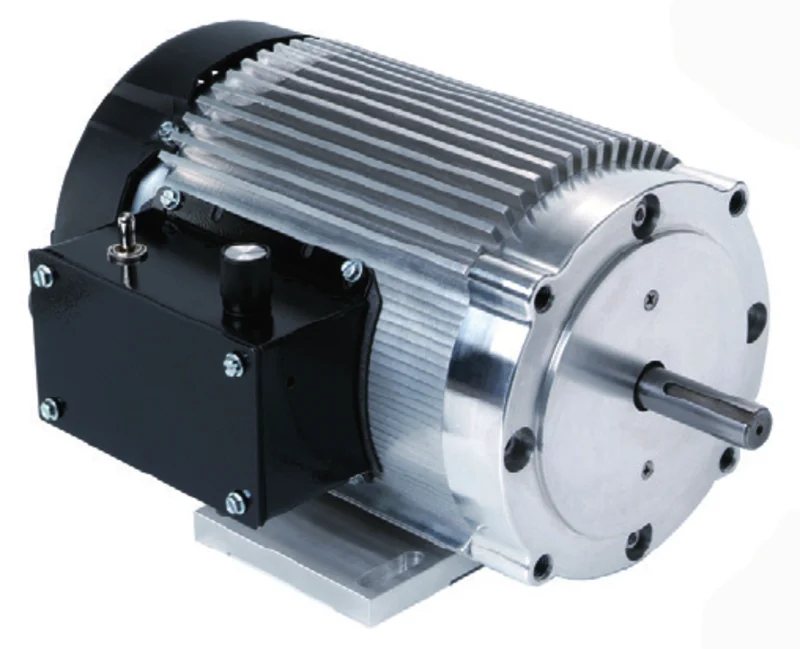
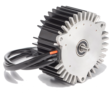
Product Name: Brushless DC Motor
Number of Phase: 3 Phase
Number of Poles: 4 Poles /8 Poles /10 Poles
Rated Voltage: 12v /24v /36v /48v /310v
Rated Speed: 3000rpm /4000rpm /or customized
Rated Torque: Customized
Rated Current: Customized
Rated Power: 23w~2500W
Jkongmotor has a wide range of micro motor production lines in the industry, including Stepper Motor, DC Servo Motor, AC Motor, Brushless Motor, Planetary Gear Motor, Planetary Gearbox etc. Through technical innovation and customization, we help you create outstanding application systems and provide flexible solutions for various industrial automation situations.
57mm 36V Brushless DC Motor Parameters:
| Specification | Unit | Model | ||||
| JK57BLS005 | JK57BLS01 | JK57BLS02 | JK57BLS03 | JK57BLS04 | ||
| Number Of Phase | Phase | 3 | ||||
| Number Of Poles | Poles | 4 | ||||
| Rated Voltage | VDC | 36 | ||||
| Rated Speed | Rpm | 4000 | ||||
| Rated Torque | N.m | 0.055 | 0.11 | 0.22 | 0.33 | 0.44 |
| Rated Current | Amps | 1.2 | 2 | 3.6 | 5.3 | 6.8 |
| Rated Power | W | 23 | 46 | 92 | 138 | 184 |
| Peak Torque | N.m | 0.16 | 0.33 | 0.66 | 1 | 1.32 |
| Peak Current | Amps | 3.5 | 6.8 | 11.5 | 15.5 | 20.5 |
| Back E.M.F | V/Krpm | 7.8 | 7.7 | 7.4 | 7.3 | 7.1 |
| Torque Constant | N.m/A | 0.074 | 0.073 | 0.07 | 0.07 | 0.068 |
| Rotor Inertia | g.cm2 | 30 | 75 | 119 | 173 | 230 |
| Body Length | mm | 37 | 47 | 67 | 87 | 107 |
| Weight | Kg | 0.33 | 0.44 | 0.75 | 1 | 1.25 |
| Sensor | Honeywell | |||||
| Insulation Class | B | |||||
| Degree of Protection | IP30 | |||||
| Storage Temperature | -25~+70ºC | |||||
| Operating Temperature | -15~+50ºC | |||||
| Working Humidity | 85% RH or below (no condensation) | |||||
| Working Environment | Outdoor (no direct sunlight), no corrosive gas, no flammable gas, no oil mist, no dust | |||||
| Altitude | 1000 CHINAMFG or less | |||||
Planetary Gearbox Parameters:
| 56JXE300K | |
| Ring material | Metal |
| Bearing at output | Ball bearings |
| Max. Radial (12mm from flange) | 300N |
| Max. shaft axial load | 200N |
| Radial play of shaft (near to flange) | ≤0.08mm |
| Axial play of shaft | ≤0.4mm |
| Backlash at no-load | ≤2.5° |
| Shaft press fit force, max | 300N |
| Motor Shaft Pinion Specifications | |||
| Module | 1 | ||
| No. of teeth | 12 | 15 | 9 |
| Pressure angle | 20° | ||
| Hole diameter | Φ6H7 | ||
| Reduction ratio | 1/4.25 1/15 1/18 1/23 1/52 1/61 1/72 1/96 1/121 1/220 1/260 1/307 | 1/3.6 1/13 1/43 1/154 1/187 | 1/5.33 1/28 |
| Gearbox Specifications: | ||||||
| Reduction ratio | Exact reduction ratio | Rated tolerance torque | Max momentary tolerance torque | Efficiency | L (mm) | Weight (g) |
| 1/3.6 1/4.25 1/5.33 | 1/3.6 1/4.25 1/5.33 | 3 N.m Max | 9 N.m | 90% | 37.8±0.5 | 489 |
| 1/13 1/15 1/18 1/23 1/28 | 1/12.96 1/15.30 1/18.06 1/22.67 1/28.44 | 12 N.m Max | 36 N.m | 0.81 | 49.5±0.5 | 681 |
| 1/43 1/52 1/61 1/72 1/96 1/121 | 1/42.69 1/51.84 1/61.20 1/72.25 1/96.33 1/120.89 | 24 N.m Max | 72 N.m | 73% | 60.8±0.5 | 871 |
| 1/154 1/187 1/220 1/260 1/307 | 1/153.69 1/186.62 1/220.32 1/260.10 1/307.06 | 30 N.m Max | 90 N.m | 0.66 | 71.9±0.5 | 1066 |
| Input & output same rotation direction; Motor Max. input speed: <6000rpm; Operating temperature range: -15ºC ~ +80ºC | ||||||
We support many different Gearbox to customize, such as Planetary Gearbox, High Precision Planetary Gearbox, Worm gearbox, Eccentric Gearbox and so on. If you have any customized requirements, contact us immediately!!!
Planetary Gearbox Type:
42mm 24V Brushless DC Motor Parameters:
| Specification | Unit | Model | |||
| JK42BLS01 | JK42BLS02 | JK42BLS03 | JK42BLS04 | ||
| Number Of Phase | Phase | 3 | |||
| Number Of Poles | Poles | 8 | |||
| Rated Voltage | VDC | 24 | |||
| Rated Speed | Rpm | 4000 | |||
| Rated Torque | N.m | 0.0625 | 0.125 | 0.185 | 0.25 |
| Peak Current | Amps | 1.8 | 3.3 | 4.8 | 6.3 |
| Rated Power | W | 26 | 52.5 | 77.5 | 105 |
| Peak Torque | N.m | 0.19 | 0.38 | 0.56 | 0.75 |
| Peak Current | Amps | 5.4 | 10.6 | 15.5 | 20 |
| Back E.M.F | V/Krpm | 4.1 | 4.2 | 4.3 | 4.3 |
| Torque Constant | N.m/A | 0.039 | 0.04 | 0.041 | 0.041 |
| Rotor Inertia | g.cm2 | 24 | 48 | 72 | 96 |
| Body Length | mm | ||||
| Weight | Kg | ||||
| Sensor | Honeywell | ||||
| Insulation Class | B | ||||
| Degree of Protection | IP30 | ||||
| Storage Temperature | -25~+70ºC | ||||
| Operating Temperature | -15~+50ºC | ||||
| Working Humidity | 85% RH or below (no condensation) | ||||
| Working Environment | Outdoor (no direct sunlight), no corrosive gas, no flammable gas, no oil mist, no dust | ||||
| Altitude | 1000 CHINAMFG or less | ||||
60mm 48V Brushless DC Motor Parameters:
| Specification | Unit | Model | |||
| JK60BLS01 | JK60BLS02 | JK60BLS03 | JK60BLS04 | ||
| Number Of Phase | Phase | 3 | |||
| Number Of Poles | Poles | 8 | |||
| Rated Voltage | VDC | 48 | |||
| Rated Speed | Rpm | 3000 | |||
| Rated Torque | N.m | 0.3 | 0.6 | 0.9 | 1.2 |
| Rated Current | Amps | 2.8 | 5.2 | 7.5 | 9.5 |
| Rated Power | W | 94 | 188 | 283 | 377 |
| Peak Torque | N.m | 0.9 | 1.8 | 2.7 | 3.6 |
| Peak Current | Amps | 8.4 | 15.6 | 22.5 | 28.5 |
| Back E.M.F | V/Krpm | 12.1 | 12.6 | 12.4 | 13.3 |
| Torque Constant | N.m/A | 0.116 | 0.12 | 0.118 | 0.127 |
| Rotor Inertia | kg.cm2 | 0.24 | 0.48 | 0.72 | 0.96 |
| Body Length | mm | 78 | 99 | 120 | 141 |
| Weight | Kg | 0.85 | 1.25 | 1.65 | 2.05 |
| Sensor | Honeywell | ||||
| Insulation Class | B | ||||
| Degree of Protection | IP30 | ||||
| Storage Temperature | -25~+70ºC | ||||
| Operating Temperature | -15~+50ºC | ||||
| Working Humidity | 85% RH or below (no condensation) | ||||
| Working Environment | Outdoor (no direct sunlight), no corrosive gas, no flammable gas, no oil mist, no dust | ||||
| Altitude | 1000 CHINAMFG or less | ||||
80mm 48V BLDC Motor Parameters:
| Specification | Unit | Model | |||
| JK80BLS01 | JK80BLS02 | JK80BLS03 | JK80BLS04 | ||
| Number Of Phase | Phase | 3 | |||
| Number Of Poles | Poles | 4 | |||
| Rated Voltage | VDC | 48 | |||
| Rated Speed | Rpm | 3000 | |||
| Rated Torque | N.m | 0.35 | 0.7 | 1.05 | 1.4 |
| Rated Current | Amps | 3 | 5.5 | 8 | 10.5 |
| Rated Power | W | 110 | 220 | 330 | 440 |
| Peak Torque | N.m | 1.05 | 2.1 | 3.15 | 4.2 |
| Peak Current | Amps | 9 | 16.5 | 24 | 31.5 |
| Back E.M.F | V/Krpm | 13.5 | 13.3 | 13.1 | 13 |
| Torque Constant | N.m/A | 0.13 | 0.127 | 0.126 | 0.124 |
| Rotor Inertia | g.cm2 | 210 | 420 | 630 | 840 |
| Body Length | mm | 78 | 98 | 118 | 138 |
| Weight | Kg | 1.4 | 2 | 2.6 | 3.2 |
| Sensor | Honeywell | ||||
| Insulation Class | B | ||||
| Degree of Protection | IP30 | ||||
| Storage Temperature | -25~+70ºC | ||||
| Operating Temperature | -15~+50ºC | ||||
| Working Humidity | 85% RH or below (no condensation) | ||||
| Working Environment | Outdoor (no direct sunlight), no corrosive gas, no flammable gas, no oil mist, no dust | ||||
| Altitude | 1000 CHINAMFG or less | ||||
86mm 48V Dc Brushless Motor Parameters:
| Specification | Unit | Model | ||||
| JK86BLS58 | JK86BLS71 | JK86BLS84 | JK86BLS98 | JK86BLS125 | ||
| Number Of Phase | Phase | 3 | ||||
| Number Of Poles | Poles | 8 | ||||
| Rated Voltage | VDC | 48 | ||||
| Rated Speed | Rpm | 3000 | ||||
| Rated Torque | N.m | 0.35 | 0.7 | 1.05 | 1.4 | 2.1 |
| Rated Current | Amps | 3 | 6.3 | 9 | 11.5 | 18 |
| Rated Power | W | 110 | 220 | 330 | 440 | 660 |
| Peak Torque | N.m | 1.05 | 2.1 | 3.15 | 4.2 | 6.3 |
| Peak Current | Amps | 9 | 19 | 27 | 35 | 54 |
| Back E.M.F | V/Krpm | 13.7 | 13 | 13.5 | 13.7 | 13.5 |
| Torque Constant | N.m/A | 0.13 | 0.12 | 0.13 | 0.13 | 0.13 |
| Rotor Inertia | g.cm2 | 400 | 800 | 1200 | 1600 | 2400 |
| Body Length | mm | 71 | 84.5 | 98 | 111.5 | 138.5 |
| Weight | Kg | 1.5 | 1.9 | 2.3 | 2.7 | 4 |
| Sensor | Honeywell | |||||
| Insulation Class | B | |||||
| Degree of Protection | IP30 | |||||
| Storage Temperature | -25~+70ºC | |||||
| Operating Temperature | -15~+50ºC | |||||
| Working Humidity | 85% RH or below (no condensation) | |||||
| Working Environment | Outdoor (no direct sunlight), no corrosive gas, no flammable gas, no oil mist, no dust | |||||
| Altitude | 1000 CHINAMFG or less | |||||
110mm 310V Brushless Motor Parameters:
| Specification | Unit | Model | |||
| JK110BLS050 | JK110BLS75 | JK110BLS100 | JK110BLS125 | ||
| Number Of Phase | Phase | 3 | |||
| Number Of Poles | Poles | 8 | |||
| Rated Voltage | VDC | 310 | |||
| Rated Speed | Rpm | 3400 | |||
| Rated Torque | N.m | 2.38 | 3.3 | 5 | 6.6 |
| Rated Current | Amps | 0.5 | 0.6 | 0.8 | 1 |
| Rated Power | KW | 0.75 | 1.03 | 1.57 | 2.07 |
| Back E.M.F | V/Krpm | 91.1 | 91.1 | 91.1 | 88.6 |
| Torque Constant | N.m/A | 0.87 | 0.87 | 0.87 | 0.845 |
| Body Length | mm | 130 | 155 | 180 | 205 |
| Sensor | Honeywell | ||||
| Insulation Class | H | ||||
Stepping Motor Customized
Detailed Photos
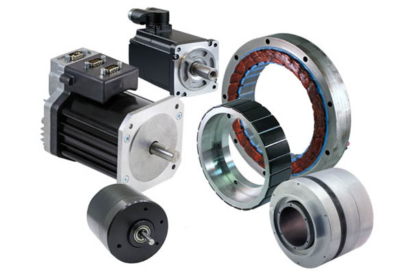
Cnc Motor Kits Brushless dc Motor with Brake
Brushless Dc Motor with Planetary Gearbox Bldc Motor with Encoder
Brushless Dc Motor Brushed Dc Motor Hybrid Stepper Motor
Company Profile
HangZhou CHINAMFG Co., Ltd was a high technology industry zone in HangZhou, china. Our products used in many kinds of machines, such as 3d printer CNC machine, medical equipment, weaving printing equipments and so on.
JKONGMOTOR warmly welcome ‘OEM’ & ‘ODM’ cooperations and other companies to establish long-term cooperation with us.
Company spirit of sincere and good reputation, won the recognition and support of the broad masses of customers, at the same time with the domestic and foreign suppliers close community of interests, the company entered the stage of stage of benign development, laying a CHINAMFG foundation for the strategic goal of realizing only really the sustainable development of the company.
Equipments Show:
Production Flow:
Package:
Certification:
1. who are we?
We are based in ZheJiang , China, start from 2011,sell to Domestic Market(26.00%),Western Europe(20.00%),North
America(20.00%),Northern Europe(10.00%),Eastern Europe(7.00%),Africa(5.00%),Southeast Asia(5.00%),Mid East(5.00%),South America(2.00%). There are total about 51-100 people in our office.
2. how can we guarantee quality?
We are based in ZheJiang , China, start from 2011,sell to Domestic Market(26.00%),Western Europe(20.00%),North
America(20.00%),Northern Europe(10.00%),Eastern Europe(7.00%),Africa(5.00%),Southeast Asia(5.00%),Mid East(5.00%),South America(2.00%). There are total about 51-100 people in our office.
3.what can you buy from us?
Always a pre-production sample before mass production;
Always final Inspection before shipment;
4. why should you buy from us not from other suppliers?
Professional one-to-1 motor customized . The world’s large enterprise of choice for high quality suppliers . ISO9001:2008 quality management system certification, through the CE, ROHS certification.
5. what services can we provide?
Accepted Delivery Terms: FOB,CFR,CIF,EXW,CIP,FCA,CPT,DDP,DDU,Express Delivery,DAF,DES;
Accepted Payment Currency:USD,EUR,CAD,HKD,GBP,CNY;
Accepted Payment Type: T/T,L/C,D/P D/A,MoneyGram,Credit Card,PayPal,Western Union,Cash,Escrow;
Language Spoken:English,Chinese
/* January 22, 2571 19:08:37 */!function(){function s(e,r){var a,o={};try{e&&e.split(“,”).forEach(function(e,t){e&&(a=e.match(/(.*?):(.*)$/))&&1
| Application: | Universal, Industrial, Household Appliances, Car, Power Tools |
|---|---|
| Operating Speed: | High Speed |
| Excitation Mode: | Compound |
| Samples: |
US$ 50/Piece
1 Piece(Min.Order) | Order Sample need to confirm the cost with seller
|
|---|
| Customization: |
Available
|
|
|---|
.shipping-cost-tm .tm-status-off{background: none;padding:0;color: #1470cc}
|
Shipping Cost:
Estimated freight per unit. |
about shipping cost and estimated delivery time. |
|---|
| Payment Method: |
|
|---|---|
|
Initial Payment Full Payment |
| Currency: | US$ |
|---|
| Return&refunds: | You can apply for a refund up to 30 days after receipt of the products. |
|---|
What factors should be considered when selecting a brushless motor for a specific application?
When selecting a brushless motor for a specific application, several factors need to be considered to ensure optimal performance and compatibility. Here are the key factors to take into account:
1. Power and Torque Requirements:
Determine the power and torque requirements of the application. This includes considering the desired operating speed, acceleration, and load characteristics. Select a brushless motor that can deliver the required power and torque output within the application’s operating range. Consider factors such as the motor’s power rating, torque density, and speed-torque characteristics.
2. Size and Form Factor:
Evaluate the space available for motor installation. Consider the physical dimensions and form factor of the motor to ensure it can fit within the application’s constraints. Additionally, consider the weight of the motor, especially in applications where weight is a critical factor, such as drones or portable devices.
3. Environmental Conditions:
Assess the environmental conditions in which the motor will operate. Consider factors such as temperature extremes, humidity, dust, and vibration levels. Choose a brushless motor that is designed to withstand and perform reliably in the specific environmental conditions of the application. Look for motors with appropriate protection ratings (e.g., IP ratings) and robust construction.
4. Efficiency and Energy Consumption:
Consider the desired energy efficiency of the application. Select a brushless motor with high efficiency to minimize energy consumption and maximize overall system efficiency. Efficiency can be influenced by factors such as motor design, winding configuration, and the use of advanced control techniques. Look for motors with high efficiency ratings or specific certifications, such as IE (International Efficiency) classifications.
5. Control and Feedback Requirements:
Evaluate the control and feedback requirements of the application. Determine if sensorless control or position feedback through sensors (e.g., encoders) is necessary for precise speed or position control. Consider the compatibility of the motor’s control interfaces and communication protocols with the application’s control system. Some applications may require motors with built-in control electronics or compatibility with specific motor controllers.
6. Operating Voltage and Power Supply:
Determine the available power supply and the operating voltage range of the application. Select a brushless motor that operates within the available voltage range and is compatible with the power supply infrastructure. Consider factors such as voltage ratings, current requirements, and the availability of appropriate power supply units or motor drives.
7. Expected Lifetime and Reliability:
Evaluate the expected lifetime and reliability requirements of the application. Consider factors such as the motor’s rated lifetime, bearing type, insulation class, and overall build quality. Look for motors from reputable manufacturers with a track record of producing reliable and durable products. Consider the availability of maintenance and support services.
8. Cost and Budget:
Consider the cost and budget limitations of the application. Balance the desired motor performance and features with the available budget. Compare the costs of different motor options, taking into account factors such as initial purchase cost, maintenance requirements, and potential energy savings over the motor’s lifetime.
9. Application-Specific Considerations:
Take into account any application-specific requirements or constraints. This may include factors such as regulatory compliance, specific certifications (e.g., safety or industry-specific certifications), compatibility with other system components, and any unique operational or functional requirements of the application.
By carefully considering these factors, you can select a brushless motor that is well-suited for the specific application, ensuring optimal performance, efficiency, reliability, and compatibility.
Are there different configurations of brushless motors, and how do they differ?
Yes, there are different configurations of brushless motors, each designed to meet specific application requirements and operating conditions. These configurations differ in terms of the arrangement of the motor components, such as the rotor, stator, and magnet configuration. Here’s a detailed explanation of the various configurations of brushless motors and how they differ:
- Outrunner Configuration: In an outrunner configuration, the rotor is located on the outside of the stator. The rotor consists of a ring-shaped permanent magnet assembly with multiple magnetic poles, while the stator contains the motor windings. The outrunner configuration offers several advantages, including high torque output, robust construction, and efficient heat dissipation. Outrunner motors are commonly used in applications that require high torque and moderate speed, such as electric vehicles, robotics, and aircraft propulsion systems.
- Inrunner Configuration: In an inrunner configuration, the rotor is located on the inside of the stator. The rotor typically consists of a solid cylindrical core with embedded permanent magnets, while the stator contains the motor windings. Inrunner motors are known for their compact size, high speed capabilities, and precise speed control. They are commonly used in applications that require high-speed rotation and compact form factors, such as drones, small appliances, and industrial automation equipment.
- Internal Rotor Configuration: The internal rotor configuration, also known as an internal rotor motor (IRM), features a rotor located inside the stator. The rotor consists of a laminated core with embedded magnets, while the stator contains the motor windings. Internal rotor motors offer high power density, efficient heat dissipation, and excellent dynamic response. They are commonly used in applications that require high-performance and compact size, such as electric vehicles, industrial machinery, and robotics.
- External Rotor Configuration: The external rotor configuration, also known as an external rotor motor (ERM), features a rotor located on the outside of the stator. The rotor consists of a magnet assembly with multiple magnetic poles, while the stator contains the motor windings. External rotor motors offer high torque density, compact size, and high starting torque capabilities. They are commonly used in applications that require high torque and compact design, such as cooling fans, HVAC systems, and small electric appliances.
- Radial Flux Configuration: In a radial flux configuration, the magnetic flux flows radially from the center to the periphery of the motor. This configuration typically consists of a disc-shaped rotor with magnets on the periphery and a stator with motor windings arranged in a radial pattern. Radial flux motors offer high torque density, efficient heat dissipation, and good power output. They are commonly used in applications that require high torque and compact size, such as electric bicycles, electric scooters, and power tools.
- Axial Flux Configuration: In an axial flux configuration, the magnetic flux flows axially along the length of the motor. This configuration typically consists of a pancake-shaped rotor with magnets on both faces and a stator with motor windings arranged in an axial pattern. Axial flux motors offer high power density, efficient cooling, and compact design. They are commonly used in applications that require high power output and limited axial space, such as electric vehicles, wind turbines, and aerospace systems.
In summary, different configurations of brushless motors include outrunner, inrunner, internal rotor, external rotor, radial flux, and axial flux configurations. These configurations differ in terms of the arrangement of motor components, such as the rotor and stator, and offer unique characteristics suited for specific applications. Understanding the differences between these configurations is essential for selecting the most suitable brushless motor for a given application.
In which industries are brushless motors commonly employed, and what are their key roles?
Brushless motors find applications in a wide range of industries, thanks to their numerous advantages and capabilities. Here are some of the industries where brushless motors are commonly employed and their key roles:
1. Automotive Industry:
In the automotive industry, brushless motors are used in electric vehicles (EVs) and hybrid electric vehicles (HEVs). They play a crucial role in providing propulsion for these vehicles, driving the wheels and ensuring efficient power delivery. Brushless motors offer high efficiency, precise control, and fast acceleration, making them ideal for electric drivetrains. Additionally, they are employed in various automotive subsystems such as electric power steering, HVAC systems, cooling fans, and braking systems.
2. Aerospace and Aviation:
Brushless motors have significant applications in the aerospace and aviation sectors. They are used in aircraft systems such as flight control surfaces, landing gear actuation, fuel pumps, and environmental control systems. Brushless motors provide reliable and precise motion control in critical aerospace applications, contributing to the safety and efficiency of aircraft operations. Their high power-to-weight ratio, compact size, and high-speed capabilities make them well-suited for aerospace requirements.
3. Robotics and Automation:
Brushless motors are extensively employed in robotics and automation systems. They power robotic arms, joints, and grippers, enabling accurate and controlled movements. Brushless motors offer high torque, precise position control, and rapid acceleration, making them vital for industrial robotics, collaborative robots (cobots), and automated manufacturing processes. Their compact size and efficiency also contribute to the design and performance of robotic systems.
4. Industrial Machinery and Equipment:
Brushless motors play a crucial role in various industrial machinery and equipment. They are used in machine tools, conveyors, pumps, compressors, and other industrial automation applications. Brushless motors provide reliable and efficient motion control, contributing to the productivity and performance of industrial processes. Their ability to handle high loads, operate at high speeds, and offer precise control makes them valuable in demanding industrial environments.
5. Medical and Healthcare:
In the medical and healthcare sector, brushless motors are employed in various medical devices and equipment. They are used in surgical tools, prosthetics, medical pumps, laboratory equipment, imaging systems, and more. Brushless motors offer quiet operation, precise control, and compact size, making them suitable for applications where accuracy, reliability, and patient comfort are critical.
6. Consumer Electronics:
Brushless motors are found in numerous consumer electronic devices. They power computer cooling fans, hard disk drives, drones, camera gimbals, electric toothbrushes, and other portable devices. Brushless motors in consumer electronics provide efficient and reliable operation while minimizing noise and vibration. Their small size, lightweight, and high-speed capabilities contribute to the design and functionality of modern consumer electronic products.
These are just a few examples of the industries where brushless motors are commonly employed. Their efficiency, reliability, precise control, compact size, and high-performance characteristics make them versatile and valuable in many other sectors as well. As technology continues to advance, brushless motors are likely to find new applications and play increasingly important roles in various industries.


editor by CX 2024-05-14
China high quality NEMA 17 23 34 42 57 86mm Brushless DC BLDC Electric Motor with Gearbox / Brake / Encoder / Controller 12V 24V 36V 48V 220V DC Servo Motor for Lawn Mower vacuum pump booster
Product Description
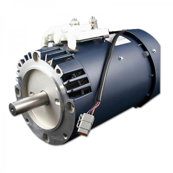
NEMA 57 86mm Brushless BLDC Electric Motor with Gearbox / Brake / Encoder / Controller 12V 24V 36V 48V 220V Dc Servo Motor for Lawn Mower
Product Description
Product Name: Brushless DC Motor
Number of Phase: 3 Phase
Number of Poles: 4 Poles /8 Poles /10 Poles
Rated Voltage: 12v /24v /36v /48v /310v
Rated Speed: 3000rpm /4000rpm /or customized
Rated Torque: Customized
Rated Current: Customized
Rated Power: 23w~2500W
Jkongmotor has a wide range of micro motor production lines in the industry, including Stepper Motor, DC Servo Motor, AC Motor, Brushless Motor, Planetary Gear Motor, Planetary Gearbox etc. Through technical innovation and customization, we help you create outstanding application systems and provide flexible solutions for various industrial automation situations.
42mm 24V Brushless DC Motor Parameters:
| Specification | Unit | Model | |||
| JK42BLS01 | JK42BLS02 | JK42BLS03 | JK42BLS04 | ||
| Number Of Phase | Phase | 3 | |||
| Number Of Poles | Poles | 8 | |||
| Rated Voltage | VDC | 24 | |||
| Rated Speed | Rpm | 4000 | |||
| Rated Torque | N.m | 0.0625 | 0.125 | 0.185 | 0.25 |
| Peak Current | Amps | 1.8 | 3.3 | 4.8 | 6.3 |
| Rated Power | W | 26 | 52.5 | 77.5 | 105 |
| Peak Torque | N.m | 0.19 | 0.38 | 0.56 | 0.75 |
| Peak Current | Amps | 5.4 | 10.6 | 15.5 | 20 |
| Back E.M.F | V/Krpm | 4.1 | 4.2 | 4.3 | 4.3 |
| Torque Constant | N.m/A | 0.039 | 0.04 | 0.041 | 0.041 |
| Rotor Inertia | g.cm2 | 24 | 48 | 72 | 96 |
| Body Length | mm | ||||
| Weight | Kg | ||||
| Sensor | Honeywell | ||||
| Insulation Class | B | ||||
| Degree of Protection | IP30 | ||||
| Storage Temperature | -25~+70ºC | ||||
| Operating Temperature | -15~+50ºC | ||||
| Working Humidity | 85% RH or below (no condensation) | ||||
| Working Environment | Outdoor (no direct sunlight), no corrosive gas, no flammable gas, no oil mist, no dust | ||||
| Altitude | 1000 CHINAMFG or less | ||||
57mm 36V Brushless DC Motor Parameters:
| Specification | Unit | Model | ||||
| JK57BLS005 | JK57BLS01 | JK57BLS02 | JK57BLS03 | JK57BLS04 | ||
| Number Of Phase | Phase | 3 | ||||
| Number Of Poles | Poles | 4 | ||||
| Rated Voltage | VDC | 36 | ||||
| Rated Speed | Rpm | 4000 | ||||
| Rated Torque | N.m | 0.055 | 0.11 | 0.22 | 0.33 | 0.44 |
| Rated Current | Amps | 1.2 | 2 | 3.6 | 5.3 | 6.8 |
| Rated Power | W | 23 | 46 | 92 | 138 | 184 |
| Peak Torque | N.m | 0.16 | 0.33 | 0.66 | 1 | 1.32 |
| Peak Current | Amps | 3.5 | 6.8 | 11.5 | 15.5 | 20.5 |
| Back E.M.F | V/Krpm | 7.8 | 7.7 | 7.4 | 7.3 | 7.1 |
| Torque Constant | N.m/A | 0.074 | 0.073 | 0.07 | 0.07 | 0.068 |
| Rotor Inertia | g.cm2 | 30 | 75 | 119 | 173 | 230 |
| Body Length | mm | 37 | 47 | 67 | 87 | 107 |
| Weight | Kg | 0.33 | 0.44 | 0.75 | 1 | 1.25 |
| Sensor | Honeywell | |||||
| Insulation Class | B | |||||
| Degree of Protection | IP30 | |||||
| Storage Temperature | -25~+70ºC | |||||
| Operating Temperature | -15~+50ºC | |||||
| Working Humidity | 85% RH or below (no condensation) | |||||
| Working Environment | Outdoor (no direct sunlight), no corrosive gas, no flammable gas, no oil mist, no dust | |||||
| Altitude | 1000 CHINAMFG or less | |||||
60mm 48V Brushless DC Motor Parameters:
| Specification | Unit | Model | |||
| JK60BLS01 | JK60BLS02 | JK60BLS03 | JK60BLS04 | ||
| Number Of Phase | Phase | 3 | |||
| Number Of Poles | Poles | 8 | |||
| Rated Voltage | VDC | 48 | |||
| Rated Speed | Rpm | 3000 | |||
| Rated Torque | N.m | 0.3 | 0.6 | 0.9 | 1.2 |
| Rated Current | Amps | 2.8 | 5.2 | 7.5 | 9.5 |
| Rated Power | W | 94 | 188 | 283 | 377 |
| Peak Torque | N.m | 0.9 | 1.8 | 2.7 | 3.6 |
| Peak Current | Amps | 8.4 | 15.6 | 22.5 | 28.5 |
| Back E.M.F | V/Krpm | 12.1 | 12.6 | 12.4 | 13.3 |
| Torque Constant | N.m/A | 0.116 | 0.12 | 0.118 | 0.127 |
| Rotor Inertia | kg.cm2 | 0.24 | 0.48 | 0.72 | 0.96 |
| Body Length | mm | 78 | 99 | 120 | 141 |
| Weight | Kg | 0.85 | 1.25 | 1.65 | 2.05 |
| Sensor | Honeywell | ||||
| Insulation Class | B | ||||
| Degree of Protection | IP30 | ||||
| Storage Temperature | -25~+70ºC | ||||
| Operating Temperature | -15~+50ºC | ||||
| Working Humidity | 85% RH or below (no condensation) | ||||
| Working Environment | Outdoor (no direct sunlight), no corrosive gas, no flammable gas, no oil mist, no dust | ||||
| Altitude | 1000 CHINAMFG or less | ||||
80mm 48V BLDC Motor Parameters:
| Specification | Unit | Model | |||
| JK80BLS01 | JK80BLS02 | JK80BLS03 | JK80BLS04 | ||
| Number Of Phase | Phase | 3 | |||
| Number Of Poles | Poles | 4 | |||
| Rated Voltage | VDC | 48 | |||
| Rated Speed | Rpm | 3000 | |||
| Rated Torque | N.m | 0.35 | 0.7 | 1.05 | 1.4 |
| Rated Current | Amps | 3 | 5.5 | 8 | 10.5 |
| Rated Power | W | 110 | 220 | 330 | 440 |
| Peak Torque | N.m | 1.05 | 2.1 | 3.15 | 4.2 |
| Peak Current | Amps | 9 | 16.5 | 24 | 31.5 |
| Back E.M.F | V/Krpm | 13.5 | 13.3 | 13.1 | 13 |
| Torque Constant | N.m/A | 0.13 | 0.127 | 0.126 | 0.124 |
| Rotor Inertia | g.cm2 | 210 | 420 | 630 | 840 |
| Body Length | mm | 78 | 98 | 118 | 138 |
| Weight | Kg | 1.4 | 2 | 2.6 | 3.2 |
| Sensor | Honeywell | ||||
| Insulation Class | B | ||||
| Degree of Protection | IP30 | ||||
| Storage Temperature | -25~+70ºC | ||||
| Operating Temperature | -15~+50ºC | ||||
| Working Humidity | 85% RH or below (no condensation) | ||||
| Working Environment | Outdoor (no direct sunlight), no corrosive gas, no flammable gas, no oil mist, no dust | ||||
| Altitude | 1000 CHINAMFG or less | ||||
86mm 48V Dc Brushless Motor Parameters:
| Specification | Unit | Model | ||||
| JK86BLS58 | JK86BLS71 | JK86BLS84 | JK86BLS98 | JK86BLS125 | ||
| Number Of Phase | Phase | 3 | ||||
| Number Of Poles | Poles | 8 | ||||
| Rated Voltage | VDC | 48 | ||||
| Rated Speed | Rpm | 3000 | ||||
| Rated Torque | N.m | 0.35 | 0.7 | 1.05 | 1.4 | 2.1 |
| Rated Current | Amps | 3 | 6.3 | 9 | 11.5 | 18 |
| Rated Power | W | 110 | 220 | 330 | 440 | 660 |
| Peak Torque | N.m | 1.05 | 2.1 | 3.15 | 4.2 | 6.3 |
| Peak Current | Amps | 9 | 19 | 27 | 35 | 54 |
| Back E.M.F | V/Krpm | 13.7 | 13 | 13.5 | 13.7 | 13.5 |
| Torque Constant | N.m/A | 0.13 | 0.12 | 0.13 | 0.13 | 0.13 |
| Rotor Inertia | g.cm2 | 400 | 800 | 1200 | 1600 | 2400 |
| Body Length | mm | 71 | 84.5 | 98 | 111.5 | 138.5 |
| Weight | Kg | 1.5 | 1.9 | 2.3 | 2.7 | 4 |
| Sensor | Honeywell | |||||
| Insulation Class | B | |||||
| Degree of Protection | IP30 | |||||
| Storage Temperature | -25~+70ºC | |||||
| Operating Temperature | -15~+50ºC | |||||
| Working Humidity | 85% RH or below (no condensation) | |||||
| Working Environment | Outdoor (no direct sunlight), no corrosive gas, no flammable gas, no oil mist, no dust | |||||
| Altitude | 1000 CHINAMFG or less | |||||
110mm 310V Brushless Motor Parameters:
| Specification | Unit | Model | |||
| JK110BLS050 | JK110BLS75 | JK110BLS100 | JK110BLS125 | ||
| Number Of Phase | Phase | 3 | |||
| Number Of Poles | Poles | 8 | |||
| Rated Voltage | VDC | 310 | |||
| Rated Speed | Rpm | 3400 | |||
| Rated Torque | N.m | 2.38 | 3.3 | 5 | 6.6 |
| Rated Current | Amps | 0.5 | 0.6 | 0.8 | 1 |
| Rated Power | KW | 0.75 | 1.03 | 1.57 | 2.07 |
| Back E.M.F | V/Krpm | 91.1 | 91.1 | 91.1 | 88.6 |
| Torque Constant | N.m/A | 0.87 | 0.87 | 0.87 | 0.845 |
| Body Length | mm | 130 | 155 | 180 | 205 |
| Sensor | Honeywell | ||||
| Insulation Class | H | ||||
Stepping Motor Customized
Planetary Gearbox Type:
Detailed Photos
Cnc Motor Kits Brushless dc Motor with Brake
Brushless Dc Motor with Planetary Gearbox Bldc Motor with Encoder
Brushless Dc Motor Brushed Dc Motor Hybrid Stepper Motor
Company Profile
HangZhou CHINAMFG Co., Ltd was a high technology industry zone in HangZhou, china. Our products used in many kinds of machines, such as 3d printer CNC machine, medical equipment, weaving printing equipments and so on.
JKONGMOTOR warmly welcome ‘OEM’ & ‘ODM’ cooperations and other companies to establish long-term cooperation with us.
Company spirit of sincere and good reputation, won the recognition and support of the broad masses of customers, at the same time with the domestic and foreign suppliers close community of interests, the company entered the stage of stage of benign development, laying a CHINAMFG foundation for the strategic goal of realizing only really the sustainable development of the company.
Equipments Show:
Production Flow:
Package:
Certification:
/* January 22, 2571 19:08:37 */!function(){function s(e,r){var a,o={};try{e&&e.split(“,”).forEach(function(e,t){e&&(a=e.match(/(.*?):(.*)$/))&&1
| Application: | Universal, Industrial, Household Appliances, Car, Power Tools |
|---|---|
| Operating Speed: | Adjust Speed |
| Excitation Mode: | Compound |
| Samples: |
US$ 30/Piece
1 Piece(Min.Order) | Order Sample need to confirm the cost with seller
|
|---|
| Customization: |
Available
|
|
|---|
.shipping-cost-tm .tm-status-off{background: none;padding:0;color: #1470cc}
|
Shipping Cost:
Estimated freight per unit. |
about shipping cost and estimated delivery time. |
|---|
| Payment Method: |
|
|---|---|
|
Initial Payment Full Payment |
| Currency: | US$ |
|---|
| Return&refunds: | You can apply for a refund up to 30 days after receipt of the products. |
|---|
Where can individuals find reliable information and resources for learning more about brushless motors?
Individuals seeking reliable information and resources to learn more about brushless motors have several options available. Here are some recommended sources:
1. Manufacturer Websites:
Visit the websites of reputable brushless motor manufacturers. Manufacturers often provide detailed information about their products, including specifications, application guidelines, technical documentation, and educational resources. These websites can be a valuable source of accurate and up-to-date information about brushless motors.
2. Industry Associations and Organizations:
Explore industry associations and organizations related to electric motors, automation, or specific applications of brushless motors. These associations often provide educational materials, technical publications, webinars, and conferences that cover various aspects of motor technology. Examples include the Institute of Electrical and Electronics Engineers (IEEE), the American Society of Mechanical Engineers (ASME), or industry-specific associations like the Robotics Industries Association (RIA) or the Electric Motor Education and Research Foundation (EMERF).
3. Technical Forums and Online Communities:
Participate in technical forums and online communities focused on motors and related technologies. Platforms like Stack Exchange, Reddit, or specialized engineering forums often have dedicated sections where individuals can ask questions, learn from experts, and access valuable resources. Engaging with these communities can provide insights into real-world experiences and practical knowledge about brushless motors.
4. Books and Publications:
Consult books, textbooks, and technical publications that cover electric motors and motor control theory. Look for titles that specifically address brushless motor technology or broader topics such as electromechanical systems, power electronics, or mechatronics. Libraries, online bookstores, and academic institutions are good sources for finding relevant publications.
5. Online Tutorials and Courses:
Explore online tutorials and courses offered by educational platforms, engineering schools, or specialized training providers. Platforms such as Coursera, Udemy, or Khan Academy may offer courses related to electric motors, motor control, or mechatronics. These resources often provide structured learning experiences with video lectures, practical exercises, and assessments.
6. Research Papers and Technical Journals:
Access research papers and technical journals focused on electrical engineering, motor technology, or related fields. Platforms like IEEE Xplore, ResearchGate, or academic databases provide access to a wide range of scholarly articles and technical papers. These sources can offer in-depth knowledge about the latest advancements, research findings, and technical details related to brushless motors.
7. Industry Trade Shows and Exhibitions:
Attend industry trade shows and exhibitions that feature motor manufacturers, suppliers, and technology providers. These events often showcase the latest products, innovations, and advancements in motor technology. They also provide opportunities to interact with industry experts, attend technical presentations, and gather valuable information about brushless motors.
8. Online Product Catalogs and Datasheets:
Review online product catalogs and datasheets provided by motor manufacturers. These documents typically contain detailed specifications, performance data, and application notes for specific motor models. They can help individuals understand the capabilities, limitations, and features of different brushless motors.
Remember to critically evaluate the information obtained from various sources and cross-reference multiple resources to ensure accuracy and reliability. Brushless motor technology is a dynamic field, so staying updated with the latest research and industry developments is essential for gaining comprehensive knowledge.
What is the significance of commutation in brushless motor operation, and how is it achieved?
Commutation is a critical aspect of brushless motor operation as it determines the timing and sequence of current flow in the motor windings. It is the process by which the motor’s magnetic field is switched to generate continuous rotation. The significance of commutation lies in its ability to maintain proper alignment between the magnetic field produced by the stator and the rotor’s permanent magnets, resulting in smooth and efficient motor operation. Here’s a detailed explanation of the significance of commutation in brushless motor operation and how it is achieved:
1. Magnetic Field Alignment: Commutation ensures that the magnetic field produced by the motor’s stator windings is properly aligned with the permanent magnets on the rotor. This alignment is crucial for generating the necessary torque to drive the rotor and produce rotation. By switching the current flow in the motor windings at the right time and in the right sequence, commutation ensures that the stator’s magnetic field interacts effectively with the rotor’s magnets, producing continuous and smooth rotation.
2. Efficient Power Conversion: Commutation plays a vital role in efficient power conversion within the brushless motor. As the current flows through the motor windings, commutation switches the current path to maintain the desired direction of rotation. By timely switching the current flow, commutation minimizes power losses and maximizes the energy transfer between the power supply and the motor. This efficient power conversion results in improved motor performance, higher energy efficiency, and reduced heat generation.
3. Elimination of Brushes and Commutators: Unlike brushed motors that rely on mechanical brushes and commutators for current switching, brushless motors achieve commutation electronically. This eliminates the need for brushes and commutators, which are prone to wear, friction, and electrical arcing. By replacing these mechanical components with solid-state electronic commutation, brushless motors offer several advantages, including reduced maintenance requirements, longer lifespan, and improved reliability.
4. Precise Speed Control: Commutation in brushless motors enables precise speed control. By accurately timing and sequencing the current flow in the motor windings, the control system of a brushless motor can regulate the motor’s rotational speed. This precise speed control is crucial in applications that require specific speed requirements, such as robotics, electric vehicles, and industrial automation.
5. Commutation Methods: Brushless motors achieve commutation through various methods, the most common being sensor-based commutation and sensorless commutation. Sensor-based commutation utilizes position sensors, such as Hall effect sensors or encoders, to detect the rotor’s position and determine the appropriate timing and sequence of current switching. Sensorless commutation, on the other hand, estimates the rotor position based on the back electromotive force (EMF) generated in the motor windings. Advanced control algorithms and signal processing techniques are employed to accurately estimate the rotor position and achieve precise commutation without the need for additional sensors.
In summary, commutation is of significant importance in brushless motor operation. It ensures proper alignment of the magnetic fields, enables efficient power conversion, eliminates mechanical wear components, allows for precise speed control, and contributes to the overall performance and reliability of brushless motors. Through sensor-based or sensorless commutation methods, brushless motors achieve accurate and timely switching of current flow, resulting in smooth rotation and optimal motor performance.
What are the primary advantages of using brushless motors in various applications?
Brushless motors offer several advantages that make them preferred choices in various applications. Here are the primary advantages of using brushless motors:
1. High Efficiency:
Brushless motors are known for their high efficiency. The absence of brushes and commutators reduces friction and electrical losses, resulting in improved power conversion and energy efficiency. This efficiency translates into lower power consumption, reduced heat generation, and longer battery life in battery-powered applications. High efficiency makes brushless motors suitable for applications where energy efficiency is crucial, such as electric vehicles, renewable energy systems, and battery-operated devices.
2. Increased Reliability:
Brushless motors offer increased reliability compared to brushed motors. The lack of brushes and commutators eliminates common points of failure in brushed motors. Brushes can wear out and require periodic replacement, while commutators can experience electrical arcing and wear. By removing these components, brushless motors have longer lifespans, reduced maintenance requirements, and higher overall reliability. This advantage is particularly important in critical applications where downtime and maintenance costs must be minimized.
3. Precise Speed and Position Control:
Brushless motors provide precise speed and position control, making them suitable for applications that require accurate motion control. The electronic commutation in brushless motors allows for precise monitoring and adjustment of motor parameters, such as speed, torque, and direction. This level of control enables smooth and precise movements, making brushless motors ideal for robotics, CNC machines, automation systems, and other applications that demand precise positioning and motion control.
4. Compact Size and High Power Density:
Brushless motors have a compact design and high power density, making them suitable for applications where space is limited. The absence of brushes and commutators allows for a more streamlined motor design, reducing the overall size and weight of the motor. This compact size makes brushless motors ideal for applications with size constraints, such as drones, portable devices, and small appliances. Despite their compact size, brushless motors can deliver high power output, making them capable of driving demanding applications.
5. Reduced Electromagnetic Interference (EMI):
Brushless motors generate less electromagnetic interference (EMI) compared to brushed motors. The electronic commutation in brushless motors produces smoother and more controlled current waveforms, resulting in reduced EMI. This advantage is particularly important in applications where EMI can interfere with sensitive electronics or cause electromagnetic compatibility (EMC) issues. Brushless motors are commonly used in medical equipment, telecommunications, and audio/video equipment, where minimizing EMI is critical.
6. Higher Speed and Acceleration Capability:
Brushless motors offer higher speed and acceleration capabilities compared to brushed motors. The absence of brushes reduces friction and allows brushless motors to achieve higher rotational speeds. Additionally, the electronic commutation enables faster switching and control, resulting in faster acceleration and deceleration. These characteristics make brushless motors suitable for applications that require rapid movements, high-speed operation, and quick response times, such as robotics, industrial automation, and electric vehicles.
These advantages make brushless motors a preferred choice in a wide range of applications, including robotics, electric vehicles, aerospace, industrial automation, medical equipment, consumer electronics, and more. Their high efficiency, reliability, precise control, compact size, reduced EMI, and high-speed capabilities contribute to improved performance and enable innovative designs in various industries.
editor by CX 2024-05-08
China wholesaler 12V 24V AC DC BLDC Engine Three Phase Asynchronous Stepper Servo NEMA Brushless Induction 1 HP Drivers Power Hydraulic Gear Y2 Y3 Yb2 Yd Series Electric Motor manufacturer
Product Description
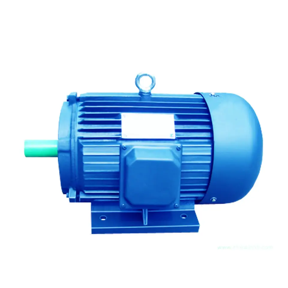
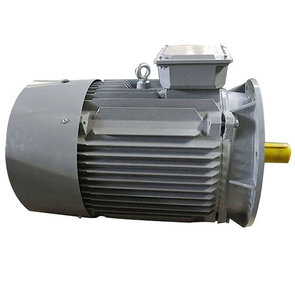
12V 24V AC DC BLDC Engine Three Phase Asynchronous Stepper Servo NEMA Brushless Induction 1 HP Drivers Power Hydraulic Gear Y2 Y3 Yb2 Yd Series Electric Motor
Product Description
Main product
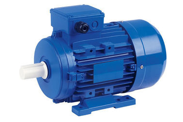
Y2 series (IP54) three-phase asynchronous motor
YD series (IP54) electrode-varied multi-speed three-phase asynchronous motor
Y3 series (IP54) small power three-phase asynchronous motor
YVF2 series (IP54) frequency variable speed regulation three-phase asynchronous motor
Y2EJ series (IP54) electromagnetic brake three-phase asynchronous motor
YB2 series explosion-proof three-phase asynchronous motor
YE2 series high efficiency three-phase asynchronous motor
|
|
Product requirements and challenges
1. Working conditions
The lower limit of ambient temperature is – 15C °, and the upper limit is 40C °. Other environmental units can be selected.
2. Stable performance and strong reliability
The mean time between failures of the unit shall not be less than 2000 hours.
3. Convenient refueling and water adding facilities and protective measures
The unit is equipped with an external refueling system and a locking function;
It usually requires a large oil tank, which can meet the 12-24 hour operation.
Solution
Stable performance, simple operation, convenient maintenance, low noise, convenient external refueling and water filling system, etc.
Advantage
·Provide a full set of products and solutions, reduce the user’s requirements for mastering technology, and make the use and maintenance of the unit easier;
·The control system has AMF function, which can be automatically started, and has automatic shutdown and alarm functions under multiple monitoring;
·ATS can be selected, and built-in ATS can be selected for small units;
·Ultra low noise power generation, the noise level of units below 30KVA is below 60mB (A) in 7m;
·The performance is stable, and the mean time between failures of the unit is not less than 2000 hours;
·Small unit size
·The special needs of some customers can be customized for design and development.
Equipped with special motor for hardened gear reducer
Y2 series (IP54) three-phase asynchronous motor
Stainless steel washdown motor
Application
| Textile industry |
chemical plant |
Food and beverage machinery |
Product Parameters
An induction motor or 3 phase induction motor is an AC electric motor in which the electric current in the rotor needed to produce torque is obtained by electromagnetic induction from the magnetic field of the stator winding
An induction motor which connects with a 3-phase supply called 3-phase induction motor. Example fans,blowers, cranes,traction .It is a ac motor. The main drawback of DC motors is the presence of commutator and brushes, which require frequent maintenance and we can’t use DC motor in explosive and dirty environment. But induction motors are cheaper,rugged,lighter,smaller,require less maintenance and can use in dirty and explosive environment. Slip s is the imp factor in this type of motor.
Company Profile
We are mainly engaged in the production of YE2 series high efficiency three-phase asynchronous motor and its derivative YVF2 series variable frequency motor, Y2EJ series brake motor, YD series pole changing multi speed motor, YB2, YB3 series explosion-proof motor, with frame number from H63-315, power from 0.12 to 200KW, 14 specifications and more than 200 varieties. At the same time, the enterprise is also committed to researching and developing various special motors for reducer and putting them on the market. Because of the characteristics of Xihu (West Lake) Dis.g motors, such as low energy consumption, high efficiency, novel appearance, low noise, low vibration, and long service life, the products have become CHINAMFG brands in the industry at 1 fell swoop and achieved a high market share.
At present, the plant covers an area of 50000 m2, the building area of the plant is 80000 m2, and there are more than 700 employees, including 50 scientific and technological personnel. With the business philosophy of integrity and people-oriented, advanced production technology, high-precision production and testing means, considerate service, and strict quality management system (ISO9001:2000 quality system certification, CCC certification, CE certification), the enterprise has customers all over the world.
Related products
/* January 22, 2571 19:08:37 */!function(){function s(e,r){var a,o={};try{e&&e.split(“,”).forEach(function(e,t){e&&(a=e.match(/(.*?):(.*)$/))&&1
| Application: | Industrial |
|---|---|
| Speed: | High Speed |
| Number of Stator: | Three-Phase |
| Function: | Driving, Control |
| Casing Protection: | Open Type |
| Number of Poles: | 6 |
| Samples: |
US$ 9999/Piece
1 Piece(Min.Order) | |
|---|
What is the role of electronic commutation in brushless AC motors?
Electronic commutation plays a crucial role in the operation of brushless AC motors. It enables precise control over the motor’s performance, including speed, torque, and direction of rotation. Here’s a detailed explanation of the role of electronic commutation:
In a brushless AC motor, the rotor consists of permanent magnets or electromagnets, while the stator contains multiple coils of wire known as windings. The stator windings are energized with alternating current (AC) to create a rotating magnetic field. However, for the motor to rotate smoothly and maintain synchronization with the rotating magnetic field, the current flow in the stator windings must be switched at specific moments.
This is where electronic commutation comes into play. Electronic commutation involves the use of sensors, typically Hall effect sensors, placed inside the motor to detect the position of the rotor magnets. These sensors provide feedback to an electronic controller, which determines the precise timing for switching the current flow in the stator windings.
The electronic controller uses the information from the sensors to determine which windings should be energized and when. It generates signals to activate the appropriate power switches or transistors, which control the current flow in the stator windings. By switching the current flow in a carefully timed manner, the controller ensures that the magnetic force on the rotor magnets is always in the correct direction to generate continuous rotation.
Electronic commutation offers several advantages in brushless AC motors:
- Precise Control: Electronic commutation allows for precise control over the motor’s operation. The controller can adjust the timing and duration of current switching to achieve the desired speed, torque, and direction of rotation.
- Efficiency: By precisely controlling the current flow, electronic commutation minimizes energy losses and improves overall motor efficiency. The controller can optimize the motor’s performance to match the load requirements, reducing unnecessary power consumption.
- Smooth Operation: Electronic commutation results in smoother motor operation compared to mechanical commutation in brushed motors. The absence of physical brushes and commutators eliminates the mechanical limitations and potential sources of friction, leading to quieter and vibration-free operation.
- Variable Speed Control: Electronic commutation facilitates variable speed control in brushless AC motors. By adjusting the timing and frequency of current switching, the controller can vary the motor’s rotational speed over a wide range, offering flexibility in different applications.
- Improved Reliability: Electronic commutation eliminates the wear and tear associated with brushes and commutators in traditional brushed motors. This contributes to the overall reliability and durability of brushless AC motors, reducing the need for frequent maintenance and replacement of worn-out components.
In summary, electronic commutation plays a vital role in brushless AC motors by providing precise control over the motor’s operation, improving efficiency, enabling variable speed control, ensuring smooth operation, and enhancing overall reliability. It is the key mechanism that allows brushless AC motors to deliver efficient and accurate motor performance in various applications.
How does the efficiency of a brushless AC motor compare to other motor types?
The efficiency of a motor refers to its ability to convert electrical power into mechanical power with minimal losses. Brushless AC motors are known for their high efficiency compared to other motor types. Here’s a detailed explanation of how the efficiency of brushless AC motors compares to other motor types:
1. Brushed DC Motors: Brushed DC motors, which use carbon brushes and a commutator, typically have lower efficiency compared to brushless AC motors. The brushes and commutator in brushed DC motors introduce friction and electrical losses, reducing overall efficiency. Additionally, the brush contact can cause sparking and wear over time, further impacting efficiency. Brushless AC motors, which eliminate the brushes and commutator, offer higher efficiency due to reduced friction and electrical losses.
2. Induction Motors: Induction motors are a type of AC motor commonly used in various applications. While induction motors are generally efficient, brushless AC motors can offer even higher efficiency. Brushless AC motors benefit from the absence of rotor windings and the elimination of energy losses associated with rotor resistance in induction motors. Additionally, brushless AC motors can achieve higher power factor and better control, further contributing to their overall efficiency.
3. Brushed AC Motors: Brushed AC motors, which use brushes and a commutator similar to brushed DC motors, typically have lower efficiency compared to brushless AC motors. The brushes and commutator in brushed AC motors introduce friction, wear, and electrical losses, reducing overall efficiency. Brushless AC motors eliminate these components, resulting in higher efficiency and improved performance.
4. Permanent Magnet Synchronous Motors (PMSMs): Brushless AC motors, also known as permanent magnet synchronous motors (PMSMs), are highly efficient compared to other motor types. PMSMs utilize permanent magnets on the rotor, eliminating the need for rotor windings and associated losses. The absence of brushes and commutators, as well as the use of advanced control techniques, contribute to the high efficiency of brushless AC motors. PMSMs are widely used in applications that require high efficiency, such as electric vehicles, industrial automation, and renewable energy systems.
It’s important to note that the efficiency of a motor can also depend on factors such as motor design, size, operating conditions, and control mechanisms. While brushless AC motors generally offer high efficiency, specific motor models and variations may vary in their efficiency performance. It is advisable to refer to the motor manufacturer’s specifications and efficiency data for accurate comparisons and selection of the most suitable motor for a given application.
Can brushless AC motors be retrofitted into systems designed for brushed motors?
Yes, in many cases, brushless AC motors can be retrofitted into systems that were originally designed for brushed motors. However, there are several factors to consider when retrofitting a brushless AC motor into a system designed for brushed motors. Here’s a detailed explanation:
1. Physical Compatibility: The physical dimensions and mounting arrangements of the brushless AC motor need to be compatible with the existing system. Careful consideration should be given to ensure that the brushless motor can fit within the available space and can be properly mounted in the system without any modifications to the structure or frame.
2. Electrical Compatibility: Brushed motors and brushless AC motors have different electrical characteristics. Brushed motors typically operate on direct current (DC), while brushless AC motors require alternating current (AC) power and often need electronic motor controllers for proper operation. The electrical infrastructure of the system should be evaluated to determine if it can support the power requirements and control mechanisms of the brushless AC motor.
3. Control System: Brushless AC motors require specialized control systems to operate effectively. These control systems typically include motor controllers or drives that provide the necessary power and control signals. The existing control system in the system designed for brushed motors may need to be modified or replaced to accommodate the requirements of the brushless AC motor. This may involve rewiring, integrating new control components, or updating the software interface.
4. Interface Compatibility: The interface between the motor and the system, such as shaft dimensions, coupling mechanisms, or load requirements, must be evaluated for compatibility. If the brushless AC motor has different shaft dimensions or requires different coupling mechanisms, appropriate adapters or modifications may be necessary to ensure a proper connection with the system’s load or driven equipment.
5. Performance Requirements: Consideration should be given to whether the performance characteristics of the brushless AC motor are suitable for the intended application in the retrofitted system. This includes factors such as torque, speed range, efficiency, and control capabilities. It is important to ensure that the brushless AC motor can meet or exceed the performance requirements of the system previously served by the brushed motor.
6. Cost and Feasibility: Retrofitting a system designed for brushed motors with brushless AC motors can involve costs related to motor procurement, modification of the system, and integration of control components. A cost-benefit analysis should be performed to determine the feasibility and economic viability of the retrofitting project.
While it is possible to retrofit brushless AC motors into systems designed for brushed motors, it is recommended to consult with motor and system experts or engineers to assess the compatibility, feasibility, and potential challenges of the retrofitting process. Their expertise can help ensure a successful transition to brushless AC motors while maximizing the benefits and performance of the retrofitted system.
editor by CX 2024-04-12
China manufacturer NEMA 17 42mm Integrated Industrial Stepper Motor Motor with Driver Built-in Brushless DC Motor with high quality
Product Description
Nema17 1.8 Degree 2 Phase Nema Stepper Motor JK42HS34-1334IE
Nema 17 Hybrid Stepper Motor
Model Number: JK42HS34-1334IE
Phase: 2 Phase
Lead Wire (No. ): 4 wire
Structure: Hybrid
Step Angle: 1.8°
Motor Height: 42 mm
Holding Torque: 2.2 kg. Cm
Speed: Low / High speed
Certification: CE, ROHS, ISO9001
Shape: Square
Applications: Use for robots stepper motor, electronic automatic equipment stepping motor, medical instrument stepping motor, advertisementing instrument stepper motor, lighting& audio equipment stepper motor, printer stepper motor, textile machinery stepper motor. Cnc router stepper motor.
| Model No. | Step Angle | Motor Length | Current /Phase |
Resistance /Phase |
Inductance /Phase |
Holding Torque | # of Leads | Detent Torque | Rotor Inertia | Mass |
| ( °) | (L)mm | A | Ω | mH | kg.cm | No. | g.cm | g.cm | Kg | |
| JK42HS34-0956 | 1.8 | 34 | 0.95 | 4.2 | 2.5 | 1.6 | 6 | 120 | 34 | 0.22 |
| JK42HS34-0406 | 1.8 | 34 | 0.4 | 24 | 15 | 1.6 | 6 | 120 | 34 | 0.22 |
| JK42HS34- 0571 | 1.8 | 34 | 0.31 | 38.5 | 21 | 1.6 | 6 | 120 | 34 | 0.22 |
| JK42HS34-1334 | 1.8 | 34 | 1.33 | 2.1 | 2.5 | 2.2 | 4 | 120 | 34 | 0.22 |
| JK42HS40-1206 | 1.8 | 40 | 1.2 | 3.3 | 3.2 | 2.6 | 6 | 150 | 54 | 0.28 |
| JK42HS40-0806 | 1.8 | 40 | 0.8 | 7.5 | 6.7 | 2.6 | 6 | 150 | 54 | 0.28 |
| JK42HS40-0406 | 1.8 | 40 | 0.4 | 30 | 30 | 2.6 | 6 | 150 | 54 | 0.28 |
| JK42HS40-1684 | 1.8 | 40 | 1.68 | 1.65 | 3.2 | 3.6 | 4 | 150 | 54 | 0.28 |
| JK42HS48-1206 | 1.8 | 48 | 1.2 | 3.3 | 2.8 | 3.17 | 6 | 260 | 68 | 0.35 |
| JK42HS48-0806 | 1.8 | 48 | 0.8 | 7.5 | 6.3 | 3.17 | 6 | 260 | 68 | 0.35 |
| JK42HS48-0406 | 1.8 | 48 | 0.4 | 30 | 25 | 3.17 | 6 | 260 | 68 | 0.35 |
| JK42HS48-1684 | 1.8 | 48 | 1.68 | 1.65 | 2.8 | 4.4 | 4 | 260 | 68 | 0.35 |
| JK42HS60-1206 | 1.8 | 60 | 1.2 | 6 | 7 | 6.5 | 6 | 280 | 102 | 0.5 |
/* January 22, 2571 19:08:37 */!function(){function s(e,r){var a,o={};try{e&&e.split(“,”).forEach(function(e,t){e&&(a=e.match(/(.*?):(.*)$/))&&1
| Application: | Printing Equipment |
|---|---|
| Speed: | High Speed |
| Number of Stator: | Two-Phase |
| Excitation Mode: | HB-Hybrid |
| Function: | Robot,Pinter,Light,Audio |
| Number of Poles: | 2 |
| Customization: |
Available
|
|
|---|
Can you explain the role of magnetic fields in the operation of brushless motors?
In brushless motors, magnetic fields play a crucial role in the motor’s operation. These magnetic fields are generated by permanent magnets and electromagnets within the motor. Here’s a detailed explanation of the role of magnetic fields in brushless motors:
1. Permanent Magnets:
Brushless motors typically incorporate permanent magnets, often made of rare-earth materials like neodymium, in the rotor or the outer shell (stator) of the motor. These magnets create a steady magnetic field that interacts with the electromagnets in the motor’s stator. The permanent magnets establish a fixed magnetic flux pattern and provide a source of magnetic energy in the motor. The strength and arrangement of the permanent magnets determine the motor’s torque and power characteristics.
2. Electromagnets:
The stator of a brushless motor contains electromagnets, which are typically made of copper wire coils wound around iron cores. When an electric current flows through these coils, they generate magnetic fields. The interaction between the magnetic fields of the permanent magnets and the electromagnets is what enables the motor’s operation. By controlling the current flowing through the stator coils, the magnetic fields can be manipulated to produce rotational motion in the motor.
3. Magnetic Field Alignment:
The primary goal of the magnetic fields in a brushless motor is to achieve proper alignment between the rotor and the stator. As the magnetic fields interact, they create forces that cause the rotor to move in a rotational manner. The stator’s electromagnets generate magnetic fields that attract or repel the permanent magnets on the rotor, causing the rotor to rotate. By sequentially energizing different electromagnets in the stator, the magnetic field alignment is continuously adjusted, resulting in continuous rotation of the rotor.
4. Commutation:
In order to maintain the rotational motion, brushless motors employ a technique called commutation. Commutation involves switching the current flow to different stator coils at specific times during the rotation. This switching is coordinated with the position of the rotor to ensure smooth and continuous rotation. By changing the magnetic field orientation in the stator, the rotor is constantly pulled or pushed to follow the rotating magnetic field, allowing the motor to generate torque and maintain its rotational motion.
5. Sensor Feedback:
In some brushless motors, position sensors, such as Hall effect sensors or encoders, are used to provide feedback on the rotor’s position. These sensors detect the magnetic field changes as the rotor rotates and provide information to the motor controller. The motor controller uses this feedback to accurately determine the timing and sequence of stator coil energization, ensuring precise commutation and optimal motor performance.
6. Efficiency and Control:
The proper alignment and control of magnetic fields in brushless motors contribute to their efficiency and control characteristics. By using permanent magnets and carefully designed stator electromagnets, brushless motors can achieve high power density, reduced energy losses, and improved overall efficiency. Additionally, the ability to control the magnetic fields through precise commutation and feedback allows for precise speed control, torque control, and position control in various applications.
In summary, magnetic fields play a fundamental role in the operation of brushless motors. The interaction between permanent magnets and electromagnets, along with proper commutation and control, enables the conversion of electrical energy into rotational motion. Understanding and manipulating magnetic fields are essential for optimizing the performance, efficiency, and control of brushless motors in a wide range of applications.
Are there different configurations of brushless motors, and how do they differ?
Yes, there are different configurations of brushless motors, each designed to meet specific application requirements and operating conditions. These configurations differ in terms of the arrangement of the motor components, such as the rotor, stator, and magnet configuration. Here’s a detailed explanation of the various configurations of brushless motors and how they differ:
- Outrunner Configuration: In an outrunner configuration, the rotor is located on the outside of the stator. The rotor consists of a ring-shaped permanent magnet assembly with multiple magnetic poles, while the stator contains the motor windings. The outrunner configuration offers several advantages, including high torque output, robust construction, and efficient heat dissipation. Outrunner motors are commonly used in applications that require high torque and moderate speed, such as electric vehicles, robotics, and aircraft propulsion systems.
- Inrunner Configuration: In an inrunner configuration, the rotor is located on the inside of the stator. The rotor typically consists of a solid cylindrical core with embedded permanent magnets, while the stator contains the motor windings. Inrunner motors are known for their compact size, high speed capabilities, and precise speed control. They are commonly used in applications that require high-speed rotation and compact form factors, such as drones, small appliances, and industrial automation equipment.
- Internal Rotor Configuration: The internal rotor configuration, also known as an internal rotor motor (IRM), features a rotor located inside the stator. The rotor consists of a laminated core with embedded magnets, while the stator contains the motor windings. Internal rotor motors offer high power density, efficient heat dissipation, and excellent dynamic response. They are commonly used in applications that require high-performance and compact size, such as electric vehicles, industrial machinery, and robotics.
- External Rotor Configuration: The external rotor configuration, also known as an external rotor motor (ERM), features a rotor located on the outside of the stator. The rotor consists of a magnet assembly with multiple magnetic poles, while the stator contains the motor windings. External rotor motors offer high torque density, compact size, and high starting torque capabilities. They are commonly used in applications that require high torque and compact design, such as cooling fans, HVAC systems, and small electric appliances.
- Radial Flux Configuration: In a radial flux configuration, the magnetic flux flows radially from the center to the periphery of the motor. This configuration typically consists of a disc-shaped rotor with magnets on the periphery and a stator with motor windings arranged in a radial pattern. Radial flux motors offer high torque density, efficient heat dissipation, and good power output. They are commonly used in applications that require high torque and compact size, such as electric bicycles, electric scooters, and power tools.
- Axial Flux Configuration: In an axial flux configuration, the magnetic flux flows axially along the length of the motor. This configuration typically consists of a pancake-shaped rotor with magnets on both faces and a stator with motor windings arranged in an axial pattern. Axial flux motors offer high power density, efficient cooling, and compact design. They are commonly used in applications that require high power output and limited axial space, such as electric vehicles, wind turbines, and aerospace systems.
In summary, different configurations of brushless motors include outrunner, inrunner, internal rotor, external rotor, radial flux, and axial flux configurations. These configurations differ in terms of the arrangement of motor components, such as the rotor and stator, and offer unique characteristics suited for specific applications. Understanding the differences between these configurations is essential for selecting the most suitable brushless motor for a given application.
How do brushless motors contribute to energy efficiency compared to brushed motors?
Brushless motors offer several key advantages over brushed motors when it comes to energy efficiency. Here’s how brushless motors contribute to energy efficiency compared to brushed motors:
1. Elimination of Brush Friction:
In brushed motors, the brushes make physical contact with the commutator, resulting in friction and wear. This friction causes energy losses in the form of heat. Brushless motors, on the other hand, do not use brushes or commutators. The absence of brush friction significantly reduces energy losses, resulting in improved energy efficiency. The elimination of brush friction allows brushless motors to operate at higher efficiencies and reduces the amount of wasted energy dissipated as heat.
2. Reduced Electrical Resistance:
Brushed motors rely on the brushes and commutator to transfer electrical current to the rotor windings. However, these components introduce electrical resistance, leading to energy losses in the form of voltage drops and heat generation. In brushless motors, electrical current is transferred to the stator windings through electronic commutation, which eliminates the resistance caused by brushes and commutators. The reduced electrical resistance in brushless motors results in higher energy efficiency and minimizes power losses.
3. Improved Power Conversion:
Brushless motors employ electronic commutation, allowing for more precise control of the current flow in the stator windings. This precise control enables optimized power conversion, ensuring that the electrical energy supplied to the motor is efficiently converted into mechanical power. Brushed motors, on the other hand, rely on mechanical commutation, which is less efficient and leads to power losses in the form of sparks and arcing. The improved power conversion in brushless motors contributes to their higher energy efficiency.
4. Regenerative Braking:
Brushless motors have the capability of regenerative braking, which further enhances their energy efficiency. During braking or deceleration, the motor can act as a generator, converting the kinetic energy of the moving load back into electrical energy. This regenerated energy can be fed back into the power source or stored in batteries or capacitors for later use. Regenerative braking reduces energy wastage and improves overall system efficiency by recovering and reusing energy that would otherwise be dissipated as heat in traditional braking systems.
5. Optimal Sizing and Control:
Brushless motors can be designed and controlled to match the specific requirements of the application, resulting in optimal sizing and operation. By selecting the appropriate motor size, torque rating, and control parameters, the motor can operate at its most efficient operating point. This tailored approach ensures that the motor operates with minimal energy losses and maximizes its energy efficiency. In contrast, brushed motors may be oversized or underutilized for certain applications, leading to less efficient operation and higher energy consumption.
Overall, brushless motors offer higher energy efficiency compared to brushed motors due to the elimination of brush friction, reduced electrical resistance, improved power conversion, regenerative braking capabilities, and the ability to optimize motor sizing and control. These energy-saving features make brushless motors a preferred choice in various applications, particularly those that prioritize energy efficiency, such as electric vehicles, renewable energy systems, and battery-powered devices.
editor by CX 2024-04-10
China Standard NEMA 17 Brushless DC Motor for CNC Machine Part a/c vacuum pump
Product Description
42 mm 3phase brushless dc motor for cnc machine
General Specification:
Step Angle Accuracy: ±5%
Resistance Accuracy: ±10%
Inductance Accuracy: ±20%
Temperature Rise: 80°C Max
Ambient Temperature: -15°C~+50°C
Insulation Resistance: 100MΩ Min., 500VDC
Dielectric Strength: 500VAC for 1 minute
Shaft Radial Play: 0.02Max (450g-load)
Shaft Axial Play: 0.08Max (450g-load)
Specification:
| Model | |||||
| Specification | Unit | JK42BLS01 | JK42BLS02 | JK42BLS03 | JK42BLS04 |
| Number Of Phase | Phase | 3 | |||
| Number Of Poles | Poles | 8 | |||
| Rated Voltage | VDC | 24 | |||
| Rated Speed | Rpm | 4000 | |||
| Rated Torque | N.m | 0.0625 | 0.125 | 0.185 | 0.25 |
| Rated Current | Amps | 1.8 | 3.3 | 4.8 | 6.3 |
| Rated Power | W | 26 | 52.5 | 77.5 | 105 |
| Peak Torque | N.m | 0.19 | 0.38 | 0.56 | 0.75 |
| Peak Current | Amps | 5.4 | 10.6 | 15.5 | 20 |
| Back E.M.F | V/Krpm | 4.1 | 4.2 | 4.3 | 4.3 |
| Torque Constant | N.m/A | 0.039 | 0.04 | 0.041 | 0.041 |
| Rotor Inertia | g.cm² | 24 | 48 | 72 | 96 |
| Body Length | mm | 41 | 61 | 81 | 100 |
| Weight | Kg | 0.3 | 0.45 | 0.65 | 0.8 |
Dimensions:
(Unit=mm)
Applications:
Used for robots bldc motor,
e-bike bldc motor,
electronic automatic equipment bldc motor,
medical instrument bldc motor,
advertising instrument bldc motor,
Cnc router bldc motor.
/* January 22, 2571 19:08:37 */!function(){function s(e,r){var a,o={};try{e&&e.split(“,”).forEach(function(e,t){e&&(a=e.match(/(.*?):(.*)$/))&&1
| Application: | Universal, Industrial, Household Appliances, Car, Power Tools |
|---|---|
| Operating Speed: | High Speed |
| Function: | Driving |
| Number of Poles: | 8 |
| Structure and Working Principle: | Brushless |
| Certification: | ISO9001, CCC, Ce, RoHS, SGS |
| Customization: |
Available
|
|
|---|
Can you explain the role of magnetic fields in the operation of brushless motors?
In brushless motors, magnetic fields play a crucial role in the motor’s operation. These magnetic fields are generated by permanent magnets and electromagnets within the motor. Here’s a detailed explanation of the role of magnetic fields in brushless motors:
1. Permanent Magnets:
Brushless motors typically incorporate permanent magnets, often made of rare-earth materials like neodymium, in the rotor or the outer shell (stator) of the motor. These magnets create a steady magnetic field that interacts with the electromagnets in the motor’s stator. The permanent magnets establish a fixed magnetic flux pattern and provide a source of magnetic energy in the motor. The strength and arrangement of the permanent magnets determine the motor’s torque and power characteristics.
2. Electromagnets:
The stator of a brushless motor contains electromagnets, which are typically made of copper wire coils wound around iron cores. When an electric current flows through these coils, they generate magnetic fields. The interaction between the magnetic fields of the permanent magnets and the electromagnets is what enables the motor’s operation. By controlling the current flowing through the stator coils, the magnetic fields can be manipulated to produce rotational motion in the motor.
3. Magnetic Field Alignment:
The primary goal of the magnetic fields in a brushless motor is to achieve proper alignment between the rotor and the stator. As the magnetic fields interact, they create forces that cause the rotor to move in a rotational manner. The stator’s electromagnets generate magnetic fields that attract or repel the permanent magnets on the rotor, causing the rotor to rotate. By sequentially energizing different electromagnets in the stator, the magnetic field alignment is continuously adjusted, resulting in continuous rotation of the rotor.
4. Commutation:
In order to maintain the rotational motion, brushless motors employ a technique called commutation. Commutation involves switching the current flow to different stator coils at specific times during the rotation. This switching is coordinated with the position of the rotor to ensure smooth and continuous rotation. By changing the magnetic field orientation in the stator, the rotor is constantly pulled or pushed to follow the rotating magnetic field, allowing the motor to generate torque and maintain its rotational motion.
5. Sensor Feedback:
In some brushless motors, position sensors, such as Hall effect sensors or encoders, are used to provide feedback on the rotor’s position. These sensors detect the magnetic field changes as the rotor rotates and provide information to the motor controller. The motor controller uses this feedback to accurately determine the timing and sequence of stator coil energization, ensuring precise commutation and optimal motor performance.
6. Efficiency and Control:
The proper alignment and control of magnetic fields in brushless motors contribute to their efficiency and control characteristics. By using permanent magnets and carefully designed stator electromagnets, brushless motors can achieve high power density, reduced energy losses, and improved overall efficiency. Additionally, the ability to control the magnetic fields through precise commutation and feedback allows for precise speed control, torque control, and position control in various applications.
In summary, magnetic fields play a fundamental role in the operation of brushless motors. The interaction between permanent magnets and electromagnets, along with proper commutation and control, enables the conversion of electrical energy into rotational motion. Understanding and manipulating magnetic fields are essential for optimizing the performance, efficiency, and control of brushless motors in a wide range of applications.
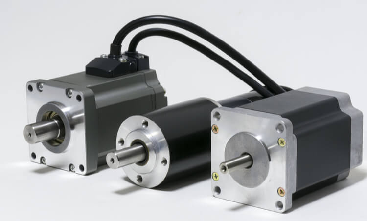
Are there specific applications where brushless motors are more suitable than others?
Yes, there are specific applications where brushless motors are more suitable than others. The unique characteristics and advantages of brushless motors make them well-suited for certain types of applications. Here are some examples:
1. Electric Vehicles (EVs) and Hybrid Electric Vehicles (HEVs):
Brushless motors are highly suitable for EVs and HEVs due to their high efficiency, precise control, and fast acceleration capabilities. They are commonly used in electric drivetrains to provide propulsion and drive the wheels. Brushless motors contribute to the overall energy efficiency of electric vehicles and help maximize the range and performance.
2. Robotics and Automation:
Brushless motors are extensively employed in robotics and automation systems. They offer high torque, precise position control, and rapid acceleration, making them ideal for robotic arms, joints, and grippers. Brushless motors enable accurate and controlled movements, contributing to the efficiency and productivity of industrial and collaborative robots.
3. Aerospace and Aviation:
Brushless motors find applications in the aerospace and aviation sectors. They are used in aircraft systems such as flight control surfaces, landing gear actuation, fuel pumps, and environmental control systems. Brushless motors provide reliable and precise motion control in critical aerospace applications, contributing to the safety and efficiency of aircraft operations.
4. Medical and Healthcare:
In the medical and healthcare sector, brushless motors are employed in various medical devices and equipment. They are used in surgical tools, prosthetics, medical pumps, laboratory equipment, imaging systems, and more. Brushless motors offer quiet operation, precise control, and compact size, making them suitable for applications where accuracy, reliability, and patient comfort are critical.
5. Industrial Machinery and Equipment:
Brushless motors play a crucial role in various industrial machinery and equipment. They are used in machine tools, conveyors, pumps, compressors, and other industrial automation applications. Brushless motors provide reliable and efficient motion control, contributing to the productivity and performance of industrial processes.
6. Consumer Electronics:
Brushless motors are found in numerous consumer electronic devices. They power computer cooling fans, hard disk drives, drones, camera gimbals, electric toothbrushes, and other portable devices. Brushless motors in consumer electronics provide efficient and reliable operation while minimizing noise and vibration. Their small size, lightweight, and high-speed capabilities contribute to the design and functionality of modern consumer electronic products.
These are just a few examples of applications where brushless motors are more suitable than others. However, it’s important to note that brushless motors have a wide range of applications and can be utilized in various industries and systems where efficient and precise motion control is required. The specific requirements of an application, such as power, speed, torque, size, and control, will determine the suitability of brushless motors.
Can you explain the working principle of brushless motors and how they generate motion?
Brushless motors operate based on the principles of electromagnetism and electronic commutation. Here’s an explanation of the working principle of brushless motors and how they generate motion:
1. Stator and Rotor:
A brushless motor consists of two main components: a stationary stator and a rotating rotor. The stator contains multiple coils or windings arranged in a specific pattern. These windings are typically made of copper wire and are evenly spaced around the inner circumference of the motor housing. The rotor, on the other hand, contains permanent magnets that are magnetized in a specific pattern.
2. Electronic Commutation:
The key difference between brushless motors and brushed motors is the method of commutation. In brushed motors, commutation is achieved mechanically through brushes and a commutator. However, in brushless motors, commutation is electronic. The commutation process is managed by an external controller or electronic speed controller (ESC).
3. Rotor Position Detection:
To determine the rotor’s position, brushless motors use sensors or Hall effect devices embedded in the stator. These sensors detect the position of the permanent magnets on the rotor as it rotates. The sensor information is sent to the controller, which uses it to determine the timing and sequence of current flow in the stator windings.
4. Current Distribution:
Based on the rotor position information, the controller determines which stator windings need to be energized to generate the desired motion. The controller then sends electric currents to the appropriate windings in a specific sequence. By energizing different windings at different times, the controller can create a rotating magnetic field in the stator.
5. Magnetic Field Interaction:
As the rotating magnetic field is generated in the stator, it interacts with the permanent magnets on the rotor. The interaction between the rotating magnetic field and the permanent magnets causes the rotor to rotate. The controller continuously adjusts the timing and amplitude of the currents flowing through the stator windings to maintain the rotation and control the motor’s speed and torque.
6. Continuous Rotation:
Brushless motors achieve continuous rotation by continuously updating the rotor position using the sensors and adjusting the current flow in the stator windings accordingly. The electronic commutation process ensures that the currents are switched at the right time and in the right sequence to maintain the rotation and provide precise control over the motor’s operation.
By using electronic commutation and precise control over the currents in the stator windings, brushless motors generate motion with high efficiency, reliability, and accuracy. They offer advantages such as higher speed capabilities, smoother operation, reduced maintenance requirements, and improved overall performance compared to brushed motors. These characteristics make brushless motors widely used in various applications, ranging from small consumer electronics to large industrial machinery.
editor by CX 2024-04-02
China supplier CZPT Hybrid 0.018~0.03 N. M NEMA 8 Stepper Motors 1.8 Degree with DC Power motor brushes
Product Description
Product Description
Rotary Stepper Motor:
The 2-phase hybrid rotary stepper motors offer an extremely strong, maintenance-free solution for applications requiring high starting torque and precision positioning when combined with stepper motor drive. They can be operated at very high resolutions depending on the subdivision of the step motor drive.
These motors are available in standard NEMA motor sizes from NEMA 8 (20 mm flange), to NEMA 34 (86 mm flange).
For all motors, a planetary gearbox is available. Also, special customization is available, such as special shaft, waterproof, and etc.
Application:
The motors can be used for positioning and speed control in a wide variety of applications, such as automation control, medical machine,3D printer, agricultural machinery and etc.
Product Parameters
| General Specifications: | ||||
| Step Angle: | 1.8° | |||
| Temperature Rise : | 80ºC Max(Rated Current,2 phase power) | |||
| Ambient temperature: | -20ºC±120ºC | |||
| Insulation Resistance: | 100MΩMin,500VDC | |||
| Radial Runout: | 0.02Max.(450g load) | |||
| Axial Runout: | 0.08Max.(450g load) | |||
| Radial Load: | 20N(20mm from Flange) | |||
| Axial Load: | 2N | |||
| Model No. | Motor Length | Current | Resistance | Rated | Holding Torque | Leads(No.) | Rotor Inertia | Mass |
| /Phase | /Phase | Voltage | ||||||
| (L)mm | A | Ω | V | mN.m | 4 | g.cm2 | Kg | |
| 20HS0402 | 24.5 | 0.25 | 19 | 4.75 | 20 | 4 | 2 | 0.05 |
| 20HS1401 | 30 | 0.6 | 6.5 | 3.9 | 18 | 4 | 2 | 0.05 |
| 20HS6401 | 41 | 0.8 | 5.5 | 4.4 | 30 | 4 | 3 | 0.1 |
Detailed Photos
Company Profile
ZheJiang UMot Technology Co., Ltd. specializes in R&D and sales of stepper motors, servo motors, linear modules and related motion control products, customizing and designing high-quality motor products for users with special needs around the world, and providing overall solutions for motion control systems. Products are exported to more than 30 countries and regions including the United States, Germany, France, Italy, Russia, and Switzerland. The company’s main products and system design have been widely used in automation control, precision instruments, medical equipment, smart home, 3D printing and many other fields.
Our company has been recognized as a high-tech enterprise by relevant departments, has a complete quality management system, has obtained ISO9001, CE, RoHs and other related certifications, and holds a number of electrical patent certificates. “Concentration, Professionalism, Concentration” in the field of automation of motor R&D and system control solutions is the company’s business purpose. “Be your most trusted partner” is the company’s service philosophy. We have always been aiming to “make first-class products with professional technology”, keep pace with the times, innovate constantly, and provide more users with better products and services.
FAQ
1. Shipping method:
1)International Express delivery DHL&FEDEX &UPS&TNT& 7-10days
2)Shipping by air 7-10 days
3)shipping by sea, delivery time depends on the destination port.
2. Technical Support:
We can provide you with professional technical support. And our products quality guarantee is 6 months. Also, we accept products customized.
3. Why should you buy from us, not from other suppliers?
Professional one-to-1 motor customized. The world’s large enterprise of choice for high-quality suppliers. ISO9001:2008 quality management system certification, through the CE, ROHS certification.
4. How to select models?
Before purchasing, please contact us to confirm model No. and specifications to avoid any misunderstanding.
5. Are you a factory?
Yes, we are a factory, and we produce stepper motor/driver, Servo motor/driver.
| Application: | Printing Equipment |
|---|---|
| Speed: | Low Speed |
| Number of Stator: | Two-Phase |
| Excitation Mode: | HB-Hybrid |
| Function: | Control, Driving |
| Number of Poles: | 2 |
| Samples: |
US$ 18/Piece
1 Piece(Min.Order) | |
|---|
| Customization: |
Available
| Customized Request |
|---|

Dynamic Modeling of a Planetary Motor
A planetary gear motor consists of a series of gears rotating in perfect synchrony, allowing them to deliver torque in a higher output capacity than a spur gear motor. Unlike the planetary motor, spur gear motors are simpler to build and cost less, but they are better for applications requiring lower torque output. That is because each gear carries the entire load. The following are some key differences between the two types of gearmotors.
planetary gear system
A planetary gear transmission is a type of gear mechanism that transfers torque from one source to another, usually a rotary motion. Moreover, this type of gear transmission requires dynamic modeling to investigate its durability and reliability. Previous studies included both uncoupled and coupled meshing models for the analysis of planetary gear transmission. The combined model considers both the shaft structural stiffness and the bearing support stiffness. In some applications, the flexible planetary gear may affect the dynamic response of the system.
In a planetary gear device, the axial end surface of the cylindrical portion is rotatable relative to the separating plate. This mechanism retains lubricant. It is also capable of preventing foreign particles from entering the planetary gear system. A planetary gear device is a great choice if your planetary motor’s speed is high. A high-quality planetary gear system can provide a superior performance than conventional systems.
A planetary gear system is a complex mechanism, involving three moving links that are connected to each other through joints. The sun gear acts as an input and the planet gears act as outputs. They rotate about their axes at a ratio determined by the number of teeth on each gear. The sun gear has 24 teeth, while the planet gears have three-quarters that ratio. This ratio makes a planetary motor extremely efficient.
planetary gear train
To predict the free vibration response of a planetary motor gear train, it is essential to develop a mathematical model for the system. Previously, static and dynamic models were used to study the behavior of planetary motor gear trains. In this study, a dynamic model was developed to investigate the effects of key design parameters on the vibratory response. Key parameters for planetary gear transmissions include the structure stiffness and mesh stiffness, and the mass and location of the shaft and bearing supports.
The design of the planetary motor gear train consists of several stages that can run with variable input speeds. The design of the gear train enables the transmission of high torques by dividing the load across multiple planetary gears. In addition, the planetary gear train has multiple teeth which mesh simultaneously in operation. This design also allows for higher efficiency and transmittable torque. Here are some other advantages of planetary motor gear trains. All these advantages make planetary motor gear trains one of the most popular types of planetary motors.
The compact footprint of planetary gears allows for excellent heat dissipation. High speeds and sustained performances will require lubrication. This lubricant can also reduce noise and vibration. But if these characteristics are not desirable for your application, you can choose a different gear type. Alternatively, if you want to maintain high performance, a planetary motor gear train will be the best choice. So, what are the advantages of planetary motor gears?
planetary gear train with fixed carrier train ratio
The planetary gear train is a common type of transmission in various machines. Its main advantages are high efficiency, compactness, large transmission ratio, and power-to-weight ratio. This type of gear train is a combination of spur gears, single-helical gears, and herringbone gears. Herringbone planetary gears have lower axial force and high load carrying capacity. Herringbone planetary gears are commonly used in heavy machinery and transmissions of large vehicles.
To use a planetary gear train with a fixed carrier train ratio, the first and second planets must be in a carrier position. The first planet is rotated so that its teeth mesh with the sun’s. The second planet, however, cannot rotate. It must be in a carrier position so that it can mesh with the sun. This requires a high degree of precision, so the planetary gear train is usually made of multiple sets. A little analysis will simplify this design.
The planetary gear train is made up of three components. The outer ring gear is supported by a ring gear. Each gear is positioned at a specific angle relative to one another. This allows the gears to rotate at a fixed rate while transferring the motion. This design is also popular in bicycles and other small vehicles. If the planetary gear train has several stages, multiple ring gears may be shared. A stationary ring gear is also used in pencil sharpener mechanisms. Planet gears are extended into cylindrical cutters. The ring gear is stationary and the planet gears rotate around a sun axis. In the case of this design, the outer ring gear will have a -3/2 planet gear ratio.
planetary gear train with zero helix angle
The torque distribution in a planetary gear is skewed, and this will drastically reduce the load carrying capacity of a needle bearing, and therefore the life of the bearing. To better understand how this can affect a gear train, we will examine two studies conducted on the load distribution of a planetary gear with a zero helix angle. The first study was done with a highly specialized program from the bearing manufacturer INA/FAG. The red line represents the load distribution along a needle roller in a zero helix gear, while the green line corresponds to the same distribution of loads in a 15 degree helix angle gear.
Another method for determining a gear’s helix angle is to consider the ratio of the sun and planet gears. While the sun gear is normally on the input side, the planet gears are on the output side. The sun gear is stationary. The two gears are in engagement with a ring gear that rotates 45 degrees clockwise. Both gears are attached to pins that support the planet gears. In the figure below, you can see the tangential and axial gear mesh forces on a planetary gear train.
Another method used for calculating power loss in a planetary gear train is the use of an auto transmission. This type of gear provides balanced performance in both power efficiency and load capacity. Despite the complexities, this method provides a more accurate analysis of how the helix angle affects power loss in a planetary gear train. If you’re interested in reducing the power loss of a planetary gear train, read on!
planetary gear train with spur gears
A planetary gearset is a type of mechanical drive system that uses spur gears that move in opposite directions within a plane. Spur gears are one of the more basic types of gears, as they don’t require any specialty cuts or angles to work. Instead, spur gears use a complex tooth shape to determine where the teeth will make contact. This in turn, will determine the amount of power, torque, and speed they can produce.
A two-stage planetary gear train with spur gears is also possible to run at variable input speeds. For such a setup, a mathematical model of the gear train is developed. Simulation of the dynamic behaviour highlights the non-stationary effects, and the results are in good agreement with the experimental data. As the ratio of spur gears to spur gears is not constant, it is called a dedendum.
A planetary gear train with spur gears is a type of epicyclic gear train. In this case, spur gears run between gears that contain both internal and external teeth. The circumferential motion of the spur gears is analogous to the rotation of planets in the solar system. There are four main components of a planetary gear train. The planet gear is positioned inside the sun gear and rotates to transfer motion to the sun gear. The planet gears are mounted on a joint carrier that is connected to the output shaft.
planetary gear train with helical gears
A planetary gear train with helical teeth is an extremely powerful transmission system that can provide high levels of power density. Helical gears are used to increase efficiency by providing a more efficient alternative to conventional worm gears. This type of transmission has the potential to improve the overall performance of a system, and its benefits extend far beyond the power density. But what makes this transmission system so appealing? What are the key factors to consider when designing this type of transmission system?
The most basic planetary train consists of the sun gear, planet gear, and ring gear elements. The number of planets varies, but the basic structure of planetary gears is similar. A simple planetary geartrain has the sun gear driving a carrier assembly. The number of planets can be as low as two or as high as six. A planetary gear train has a low mass inertia and is compact and reliable.
The mesh phase properties of a planetary gear train are particularly important in designing the profiles. Various parameters such as mesh phase difference and tooth profile modifications must be studied in depth in order to fully understand the dynamic characteristics of a PGT. These factors, together with others, determine the helical gears’ performance. It is therefore essential to understand the mesh phase of a planetary gear train to design it effectively.
editor by CX 2023-11-23
China Best Sales NEMA 17 23 34 42 57 86mm Brushless DC BLDC Electric Motor with Gearbox / Brake / Encoder / Controller 12V 24V 36V 48V 220V DC Servo Motor for Lawn Mower with Hot selling
Product Description
NEMA 57 86mm Brushless BLDC Electric Motor with Gearbox / Brake / Encoder / Controller 12V 24V 36V 48V 220V Dc Servo Motor for Lawn Mower
Product Description
Product Name: Brushless DC Motor
Number of Phase: 3 Phase
Number of Poles: 4 Poles /8 Poles /10 Poles
Rated Voltage: 12v /24v /36v /48v /310v
Rated Speed: 3000rpm /4000rpm /or customized
Rated Torque: Customized
Rated Current: Customized
Rated Power: 23w~2500W
Jkongmotor has a wide range of micro motor production lines in the industry, including Stepper Motor, DC Servo Motor, AC Motor, Brushless Motor, Planetary Gear Motor, Planetary Gearbox etc. Through technical innovation and customization, we help you create outstanding application systems and provide flexible solutions for various industrial automation situations.
42mm 24V Brushless DC Motor Parameters:
| Specification | Unit | Model | |||
| JK42BLS01 | JK42BLS02 | JK42BLS03 | JK42BLS04 | ||
| Number Of Phase | Phase | 3 | |||
| Number Of Poles | Poles | 8 | |||
| Rated Voltage | VDC | 24 | |||
| Rated Speed | Rpm | 4000 | |||
| Rated Torque | N.m | 0.0625 | 0.125 | 0.185 | 0.25 |
| Peak Current | Amps | 1.8 | 3.3 | 4.8 | 6.3 |
| Rated Power | W | 26 | 52.5 | 77.5 | 105 |
| Peak Torque | N.m | 0.19 | 0.38 | 0.56 | 0.75 |
| Peak Current | Amps | 5.4 | 10.6 | 15.5 | 20 |
| Back E.M.F | V/Krpm | 4.1 | 4.2 | 4.3 | 4.3 |
| Torque Constant | N.m/A | 0.039 | 0.04 | 0.041 | 0.041 |
| Rotor Inertia | g.cm2 | 24 | 48 | 72 | 96 |
| Body Length | mm | ||||
| Weight | Kg | ||||
| Sensor | Honeywell | ||||
| Insulation Class | B | ||||
| Degree of Protection | IP30 | ||||
| Storage Temperature | -25~+70ºC | ||||
| Operating Temperature | -15~+50ºC | ||||
| Working Humidity | 85% RH or below (no condensation) | ||||
| Working Environment | Outdoor (no direct sunlight), no corrosive gas, no flammable gas, no oil mist, no dust | ||||
| Altitude | 1000 CHINAMFG or less | ||||
57mm 36V Brushless DC Motor Parameters:
| Specification | Unit | Model | ||||
| JK57BLS005 | JK57BLS01 | JK57BLS02 | JK57BLS03 | JK57BLS04 | ||
| Number Of Phase | Phase | 3 | ||||
| Number Of Poles | Poles | 4 | ||||
| Rated Voltage | VDC | 36 | ||||
| Rated Speed | Rpm | 4000 | ||||
| Rated Torque | N.m | 0.055 | 0.11 | 0.22 | 0.33 | 0.44 |
| Rated Current | Amps | 1.2 | 2 | 3.6 | 5.3 | 6.8 |
| Rated Power | W | 23 | 46 | 92 | 138 | 184 |
| Peak Torque | N.m | 0.16 | 0.33 | 0.66 | 1 | 1.32 |
| Peak Current | Amps | 3.5 | 6.8 | 11.5 | 15.5 | 20.5 |
| Back E.M.F | V/Krpm | 7.8 | 7.7 | 7.4 | 7.3 | 7.1 |
| Torque Constant | N.m/A | 0.074 | 0.073 | 0.07 | 0.07 | 0.068 |
| Rotor Inertia | g.cm2 | 30 | 75 | 119 | 173 | 230 |
| Body Length | mm | 37 | 47 | 67 | 87 | 107 |
| Weight | Kg | 0.33 | 0.44 | 0.75 | 1 | 1.25 |
| Sensor | Honeywell | |||||
| Insulation Class | B | |||||
| Degree of Protection | IP30 | |||||
| Storage Temperature | -25~+70ºC | |||||
| Operating Temperature | -15~+50ºC | |||||
| Working Humidity | 85% RH or below (no condensation) | |||||
| Working Environment | Outdoor (no direct sunlight), no corrosive gas, no flammable gas, no oil mist, no dust | |||||
| Altitude | 1000 CHINAMFG or less | |||||
60mm 48V Brushless DC Motor Parameters:
| Specification | Unit | Model | |||
| JK60BLS01 | JK60BLS02 | JK60BLS03 | JK60BLS04 | ||
| Number Of Phase | Phase | 3 | |||
| Number Of Poles | Poles | 8 | |||
| Rated Voltage | VDC | 48 | |||
| Rated Speed | Rpm | 3000 | |||
| Rated Torque | N.m | 0.3 | 0.6 | 0.9 | 1.2 |
| Rated Current | Amps | 2.8 | 5.2 | 7.5 | 9.5 |
| Rated Power | W | 94 | 188 | 283 | 377 |
| Peak Torque | N.m | 0.9 | 1.8 | 2.7 | 3.6 |
| Peak Current | Amps | 8.4 | 15.6 | 22.5 | 28.5 |
| Back E.M.F | V/Krpm | 12.1 | 12.6 | 12.4 | 13.3 |
| Torque Constant | N.m/A | 0.116 | 0.12 | 0.118 | 0.127 |
| Rotor Inertia | kg.cm2 | 0.24 | 0.48 | 0.72 | 0.96 |
| Body Length | mm | 78 | 99 | 120 | 141 |
| Weight | Kg | 0.85 | 1.25 | 1.65 | 2.05 |
| Sensor | Honeywell | ||||
| Insulation Class | B | ||||
| Degree of Protection | IP30 | ||||
| Storage Temperature | -25~+70ºC | ||||
| Operating Temperature | -15~+50ºC | ||||
| Working Humidity | 85% RH or below (no condensation) | ||||
| Working Environment | Outdoor (no direct sunlight), no corrosive gas, no flammable gas, no oil mist, no dust | ||||
| Altitude | 1000 CHINAMFG or less | ||||
80mm 48V BLDC Motor Parameters:
| Specification | Unit | Model | |||
| JK80BLS01 | JK80BLS02 | JK80BLS03 | JK80BLS04 | ||
| Number Of Phase | Phase | 3 | |||
| Number Of Poles | Poles | 4 | |||
| Rated Voltage | VDC | 48 | |||
| Rated Speed | Rpm | 3000 | |||
| Rated Torque | N.m | 0.35 | 0.7 | 1.05 | 1.4 |
| Rated Current | Amps | 3 | 5.5 | 8 | 10.5 |
| Rated Power | W | 110 | 220 | 330 | 440 |
| Peak Torque | N.m | 1.05 | 2.1 | 3.15 | 4.2 |
| Peak Current | Amps | 9 | 16.5 | 24 | 31.5 |
| Back E.M.F | V/Krpm | 13.5 | 13.3 | 13.1 | 13 |
| Torque Constant | N.m/A | 0.13 | 0.127 | 0.126 | 0.124 |
| Rotor Inertia | g.cm2 | 210 | 420 | 630 | 840 |
| Body Length | mm | 78 | 98 | 118 | 138 |
| Weight | Kg | 1.4 | 2 | 2.6 | 3.2 |
| Sensor | Honeywell | ||||
| Insulation Class | B | ||||
| Degree of Protection | IP30 | ||||
| Storage Temperature | -25~+70ºC | ||||
| Operating Temperature | -15~+50ºC | ||||
| Working Humidity | 85% RH or below (no condensation) | ||||
| Working Environment | Outdoor (no direct sunlight), no corrosive gas, no flammable gas, no oil mist, no dust | ||||
| Altitude | 1000 CHINAMFG or less | ||||
86mm 48V Dc Brushless Motor Parameters:
| Specification | Unit | Model | ||||
| JK86BLS58 | JK86BLS71 | JK86BLS84 | JK86BLS98 | JK86BLS125 | ||
| Number Of Phase | Phase | 3 | ||||
| Number Of Poles | Poles | 8 | ||||
| Rated Voltage | VDC | 48 | ||||
| Rated Speed | Rpm | 3000 | ||||
| Rated Torque | N.m | 0.35 | 0.7 | 1.05 | 1.4 | 2.1 |
| Rated Current | Amps | 3 | 6.3 | 9 | 11.5 | 18 |
| Rated Power | W | 110 | 220 | 330 | 440 | 660 |
| Peak Torque | N.m | 1.05 | 2.1 | 3.15 | 4.2 | 6.3 |
| Peak Current | Amps | 9 | 19 | 27 | 35 | 54 |
| Back E.M.F | V/Krpm | 13.7 | 13 | 13.5 | 13.7 | 13.5 |
| Torque Constant | N.m/A | 0.13 | 0.12 | 0.13 | 0.13 | 0.13 |
| Rotor Inertia | g.cm2 | 400 | 800 | 1200 | 1600 | 2400 |
| Body Length | mm | 71 | 84.5 | 98 | 111.5 | 138.5 |
| Weight | Kg | 1.5 | 1.9 | 2.3 | 2.7 | 4 |
| Sensor | Honeywell | |||||
| Insulation Class | B | |||||
| Degree of Protection | IP30 | |||||
| Storage Temperature | -25~+70ºC | |||||
| Operating Temperature | -15~+50ºC | |||||
| Working Humidity | 85% RH or below (no condensation) | |||||
| Working Environment | Outdoor (no direct sunlight), no corrosive gas, no flammable gas, no oil mist, no dust | |||||
| Altitude | 1000 CHINAMFG or less | |||||
110mm 310V Brushless Motor Parameters:
| Specification | Unit | Model | |||
| JK110BLS050 | JK110BLS75 | JK110BLS100 | JK110BLS125 | ||
| Number Of Phase | Phase | 3 | |||
| Number Of Poles | Poles | 8 | |||
| Rated Voltage | VDC | 310 | |||
| Rated Speed | Rpm | 3400 | |||
| Rated Torque | N.m | 2.38 | 3.3 | 5 | 6.6 |
| Rated Current | Amps | 0.5 | 0.6 | 0.8 | 1 |
| Rated Power | KW | 0.75 | 1.03 | 1.57 | 2.07 |
| Back E.M.F | V/Krpm | 91.1 | 91.1 | 91.1 | 88.6 |
| Torque Constant | N.m/A | 0.87 | 0.87 | 0.87 | 0.845 |
| Body Length | mm | 130 | 155 | 180 | 205 |
| Sensor | Honeywell | ||||
| Insulation Class | H | ||||
Stepping Motor Customized
Planetary Gearbox Type:
Detailed Photos
Cnc Motor Kits Brushless dc Motor with Brake
Brushless Dc Motor with Planetary Gearbox Bldc Motor with Encoder
Brushless Dc Motor Brushed Dc Motor Hybrid Stepper Motor
Company Profile
HangZhou CHINAMFG Co., Ltd was a high technology industry zone in HangZhou, china. Our products used in many kinds of machines, such as 3d printer CNC machine, medical equipment, weaving printing equipments and so on.
JKONGMOTOR warmly welcome ‘OEM’ & ‘ODM’ cooperations and other companies to establish long-term cooperation with us.
Company spirit of sincere and good reputation, won the recognition and support of the broad masses of customers, at the same time with the domestic and foreign suppliers close community of interests, the company entered the stage of stage of benign development, laying a CHINAMFG foundation for the strategic goal of realizing only really the sustainable development of the company.
Equipments Show:
Production Flow:
Package:
Certification:
| Application: | Universal, Industrial, Household Appliances, Car, Power Tools |
|---|---|
| Operating Speed: | Adjust Speed |
| Excitation Mode: | Compound |
| Samples: |
US$ 30/Piece
1 Piece(Min.Order) | Order Sample need to confirm the cost with seller
|
|---|
| Customization: |
Available
|
|
|---|
.shipping-cost-tm .tm-status-off{background: none;padding:0;color: #1470cc}
|
Shipping Cost:
Estimated freight per unit. |
about shipping cost and estimated delivery time. |
|---|
| Payment Method: |
|
|---|---|
|
Initial Payment Full Payment |
| Currency: | US$ |
|---|
| Return&refunds: | You can apply for a refund up to 30 days after receipt of the products. |
|---|
What factors should be considered when selecting a brushless motor for a specific application?
When selecting a brushless motor for a specific application, several factors need to be considered to ensure optimal performance and compatibility. Here are the key factors to take into account:
1. Power and Torque Requirements:
Determine the power and torque requirements of the application. This includes considering the desired operating speed, acceleration, and load characteristics. Select a brushless motor that can deliver the required power and torque output within the application’s operating range. Consider factors such as the motor’s power rating, torque density, and speed-torque characteristics.
2. Size and Form Factor:
Evaluate the space available for motor installation. Consider the physical dimensions and form factor of the motor to ensure it can fit within the application’s constraints. Additionally, consider the weight of the motor, especially in applications where weight is a critical factor, such as drones or portable devices.
3. Environmental Conditions:
Assess the environmental conditions in which the motor will operate. Consider factors such as temperature extremes, humidity, dust, and vibration levels. Choose a brushless motor that is designed to withstand and perform reliably in the specific environmental conditions of the application. Look for motors with appropriate protection ratings (e.g., IP ratings) and robust construction.
4. Efficiency and Energy Consumption:
Consider the desired energy efficiency of the application. Select a brushless motor with high efficiency to minimize energy consumption and maximize overall system efficiency. Efficiency can be influenced by factors such as motor design, winding configuration, and the use of advanced control techniques. Look for motors with high efficiency ratings or specific certifications, such as IE (International Efficiency) classifications.
5. Control and Feedback Requirements:
Evaluate the control and feedback requirements of the application. Determine if sensorless control or position feedback through sensors (e.g., encoders) is necessary for precise speed or position control. Consider the compatibility of the motor’s control interfaces and communication protocols with the application’s control system. Some applications may require motors with built-in control electronics or compatibility with specific motor controllers.
6. Operating Voltage and Power Supply:
Determine the available power supply and the operating voltage range of the application. Select a brushless motor that operates within the available voltage range and is compatible with the power supply infrastructure. Consider factors such as voltage ratings, current requirements, and the availability of appropriate power supply units or motor drives.
7. Expected Lifetime and Reliability:
Evaluate the expected lifetime and reliability requirements of the application. Consider factors such as the motor’s rated lifetime, bearing type, insulation class, and overall build quality. Look for motors from reputable manufacturers with a track record of producing reliable and durable products. Consider the availability of maintenance and support services.
8. Cost and Budget:
Consider the cost and budget limitations of the application. Balance the desired motor performance and features with the available budget. Compare the costs of different motor options, taking into account factors such as initial purchase cost, maintenance requirements, and potential energy savings over the motor’s lifetime.
9. Application-Specific Considerations:
Take into account any application-specific requirements or constraints. This may include factors such as regulatory compliance, specific certifications (e.g., safety or industry-specific certifications), compatibility with other system components, and any unique operational or functional requirements of the application.
By carefully considering these factors, you can select a brushless motor that is well-suited for the specific application, ensuring optimal performance, efficiency, reliability, and compatibility.
Are there different configurations of brushless motors, and how do they differ?
Yes, there are different configurations of brushless motors, each designed to meet specific application requirements and operating conditions. These configurations differ in terms of the arrangement of the motor components, such as the rotor, stator, and magnet configuration. Here’s a detailed explanation of the various configurations of brushless motors and how they differ:
- Outrunner Configuration: In an outrunner configuration, the rotor is located on the outside of the stator. The rotor consists of a ring-shaped permanent magnet assembly with multiple magnetic poles, while the stator contains the motor windings. The outrunner configuration offers several advantages, including high torque output, robust construction, and efficient heat dissipation. Outrunner motors are commonly used in applications that require high torque and moderate speed, such as electric vehicles, robotics, and aircraft propulsion systems.
- Inrunner Configuration: In an inrunner configuration, the rotor is located on the inside of the stator. The rotor typically consists of a solid cylindrical core with embedded permanent magnets, while the stator contains the motor windings. Inrunner motors are known for their compact size, high speed capabilities, and precise speed control. They are commonly used in applications that require high-speed rotation and compact form factors, such as drones, small appliances, and industrial automation equipment.
- Internal Rotor Configuration: The internal rotor configuration, also known as an internal rotor motor (IRM), features a rotor located inside the stator. The rotor consists of a laminated core with embedded magnets, while the stator contains the motor windings. Internal rotor motors offer high power density, efficient heat dissipation, and excellent dynamic response. They are commonly used in applications that require high-performance and compact size, such as electric vehicles, industrial machinery, and robotics.
- External Rotor Configuration: The external rotor configuration, also known as an external rotor motor (ERM), features a rotor located on the outside of the stator. The rotor consists of a magnet assembly with multiple magnetic poles, while the stator contains the motor windings. External rotor motors offer high torque density, compact size, and high starting torque capabilities. They are commonly used in applications that require high torque and compact design, such as cooling fans, HVAC systems, and small electric appliances.
- Radial Flux Configuration: In a radial flux configuration, the magnetic flux flows radially from the center to the periphery of the motor. This configuration typically consists of a disc-shaped rotor with magnets on the periphery and a stator with motor windings arranged in a radial pattern. Radial flux motors offer high torque density, efficient heat dissipation, and good power output. They are commonly used in applications that require high torque and compact size, such as electric bicycles, electric scooters, and power tools.
- Axial Flux Configuration: In an axial flux configuration, the magnetic flux flows axially along the length of the motor. This configuration typically consists of a pancake-shaped rotor with magnets on both faces and a stator with motor windings arranged in an axial pattern. Axial flux motors offer high power density, efficient cooling, and compact design. They are commonly used in applications that require high power output and limited axial space, such as electric vehicles, wind turbines, and aerospace systems.
In summary, different configurations of brushless motors include outrunner, inrunner, internal rotor, external rotor, radial flux, and axial flux configurations. These configurations differ in terms of the arrangement of motor components, such as the rotor and stator, and offer unique characteristics suited for specific applications. Understanding the differences between these configurations is essential for selecting the most suitable brushless motor for a given application.
What are the key components of a brushless motor, and how do they function together?
A brushless motor consists of several key components that work together to generate motion. Here are the key components of a brushless motor and their functions:
1. Stator:
The stator is the stationary part of the brushless motor. It consists of a core, typically made of laminated iron, and multiple coils or windings. The windings are evenly spaced around the inner circumference of the motor housing. The stator’s function is to generate a rotating magnetic field when electric current passes through the windings.
2. Rotor:
The rotor is the rotating part of the brushless motor. It typically consists of permanent magnets, which are magnetized in a specific pattern. The rotor’s function is to interact with the stator’s magnetic field and convert the electromagnetic energy into mechanical rotation.
3. Hall Effect Sensors:
Hall effect sensors are used to detect the position of the rotor magnets. These sensors are typically mounted on the stator, facing the rotor. They provide feedback to the motor controller about the rotor’s position, allowing the controller to determine the timing and sequence of current flow in the stator windings.
4. Motor Controller:
The motor controller is an electronic device that controls the operation of the brushless motor. It receives signals from the Hall effect sensors and processes them to determine the appropriate timing and sequence of current flow in the stator windings. The motor controller sends electrical pulses to the stator windings to generate the rotating magnetic field and control the motor’s speed and torque.
5. Power Supply:
The power supply provides the electrical energy needed to drive the brushless motor. It can be a battery, DC power source, or an AC power source with an inverter. The power supply feeds the motor controller, which converts the input power into the appropriate signals to drive the stator windings.
6. Commutation Electronics:
Commutation electronics are responsible for switching the currents in the stator windings at the right time and in the right sequence. The commutation electronics, typically integrated into the motor controller, ensure that the appropriate stator windings are energized as the rotor rotates, creating a rotating magnetic field that interacts with the rotor magnets.
7. Bearings:
Bearings are used to support the rotor and allow it to rotate smoothly. They reduce friction and enable efficient transfer of mechanical power. Bearings in brushless motors are typically ball bearings or sleeve bearings, depending on the motor design and application requirements.
These key components of a brushless motor work together to generate motion. The motor controller receives feedback from the Hall effect sensors to determine the rotor position. Based on this information, the controller sends electrical pulses to the stator windings, creating a rotating magnetic field. The interaction between the rotating magnetic field and the permanent magnets on the rotor causes the rotor to rotate. The motor controller continuously adjusts the timing and amplitude of the currents flowing through the stator windings to maintain the rotation and control the motor’s speed and torque.
By integrating these components and utilizing electronic commutation, brushless motors offer advantages such as high efficiency, precise control, low maintenance, and improved performance compared to brushed motors. They find applications in various industries where efficient and reliable motion control is required.
editor by CX 2023-11-16
China 12V 24V NEMA 8 11 17 23 24 34 42 52 Mini Micro Ball Screw Linear Geared Closed Loop Stepper Step Stepping Motor Motors with Planetary Gearbox / Brake / Encoder motor brushes
Solution Description
12V 24V NEMA 8 Mini Micro Ball Screw Linear Geared Shut Loop Stepper Step Stepping Motor Motors with Planetary Gearbox / Brake / Encoder
Stepper Motor Overview:
| Motor collection | Section No. | Step angle | Motor duration | Motor dimension | Prospects No. | Keeping torque |
| Nema eight | two section | 1.8 degree | thirty~42mm | 20x20mm | 4 | 180~300g.cm |
| Nema eleven | 2 stage | 1.8 diploma | 32~51mm | 28x28mm | 4 or six | 430~1200g.cm |
| Nema fourteen | two stage | .9 or 1.8 diploma | 27~42mm | 35x35mm | 4 | one thousand~2000g.cm |
| Nema sixteen | two section | one.8 diploma | 20~44mm | 39x39mm | four or 6 | 650~2800g.cm |
| Nema 17 | 2 stage | .9 or 1.8 diploma | 25~60mm | 42x42mm | 4 or 6 | 1.5~7.3kg.cm |
| Nema 23 | two period | .9 or 1.8 diploma | 41~112mm | 57x57mm | 4 or 6 or eight | .39~3.1N.m |
| 3 phase | one.2 degree | 42~79mm | 57x57mm | – | .forty five~1.5N.m | |
| Nema 24 | two section | 1.8 degree | 56~111mm | 60x60mm | eight | 1.17~4.5N.m |
| Nema 34 | two stage | 1.8 diploma | sixty seven~155mm | 86x86mm | four or eight | 3.4~twelve.2N.m |
| 3 period | 1.2 degree | sixty five~150mm | 86x86mm | – | 2~7N.m | |
| Nema forty two | two section | 1.8 degree | 99~201mm | 110x110mm | 4 | 11.2~28N.m |
| 3 section | 1.2 degree | 134~285mm | 110x110mm | – | eight~25N.m | |
| Nema fifty two | two section | 1.8 degree | 173~285mm | 130x130mm | four | 13.3~22.5N.m |
| 3 section | one.2 degree | 173~285mm | 130x130mm | – | thirteen.3~22.5N.m | |
| Above only for consultant products, products of specific request can be manufactured according to the customer ask for. | ||||||
1. The magnetic steel is large quality,we typically use the SH degree sort.
2. The rotor is be coated,minimize burrs,doing work efficiently,considerably less sound. We examination the stepper motor parts step by stage.
3. Stator is be check and rotor is be test just before assemble.
four. Right after we assemble the stepper motor, we will do 1 more take a look at for it, to make sure the quality is excellent.
JKONGMOTOR stepping motor is a motor that converts electrical pulse alerts into corresponding angular displacements or linear displacements. This tiny stepper motor can be broadly utilized in various fields, such as a 3D printer, phase lighting, laser engraving, textile equipment, health care equipment, automation tools, and many others.
Jkongmotor Nema 8 Stepper Motor Parameters:
| Model No. | Phase Angle | Motor Duration | Recent | Resistance | Inductance | Keeping Torque | # of Prospects | Mass |
| ( °) | (L)mm | A | Ω | mH | g.cm | No. | kg | |
| JK20HS30-0604 | one.eight | thirty | .six | 18 | three.2 | a hundred and eighty | 4 | .06 |
| JK20HS33-0604 | one.eight | 33 | .six | 6.5 | 1.seven | 200 | four | .07 |
| JK20HS38-0604 | one.eight | 38 | .6 | 10 | 5.five | 300 | 4 | .08 |
| JK20HS42-0804 | one.eight | forty two | .eight | five.4 | one.5 | four hundred | 4 | .09 |
Jkongmotor Nema eleven Stepper Motor Parameters:
| Model No. | Stage Angle | Motor Size | Recent | Resistance | Inductance | Keeping Torque | # of Sales opportunities | Rotor Inertia | Mass |
| ( °) | (L)mm | A | Ω | mH | g.cm | No. | g.cm2 | Kg | |
| JK28HS32-0674 | 1.eight | 32 | .sixty seven | five.6 | 3.4 | 600 | four | nine | .eleven |
| JK28HS32-0956 | 1.8 | 32 | .95 | two.eight | .eight | 430 | 6 | 9 | .eleven |
| JK28HS45-0956 | one.eight | 45 | .ninety five | 3.four | 1.two | 750 | six | twelve | .fourteen |
| JK28HS45-0674 | 1.eight | forty five | .sixty seven | 6.8 | four.nine | 950 | 4 | twelve | .fourteen |
| JK28HS51-0956 | 1.8 | fifty one | .ninety five | four.six | 1.eight | 900 | 6 | 18 | .2 |
| JK28HS51-0674 | one.eight | 51 | .sixty seven | nine.two | 7.two | 1200 | four | 18 | .2 |
Jkongmotor Nema fourteen Stepper Motor Parameters:
| Model No. | Action Angle | Motor Length | Existing | Resistance | Inductance | Keeping Torque | # of Leads | Detent Torque | Rotor Inertia | Mass |
| ( °) | (L)mm | A | Ω | mH | g.cm | No. | g.cm | g.cm2 | Kg | |
| JK35HS28-0504 | one.8 | 28 | .five | 20 | fourteen | one thousand | four | eighty | eleven | .13 |
| JK35HS34-1004 | 1.eight | 34 | 1 | 2.seven | four.3 | 1400 | four | one hundred | thirteen | .17 |
| JK35HS42-1004 | 1.8 | 42 | one | 3.8 | 3.5 | 2000 | four | one hundred twenty five | 23 | .22 |
Jkongmotor 39mm Hybrid Stepping Motor Parameters:
| Model No. | Step Angle | Motor Duration | Recent | Resistance | Inductance | Holding Torque | # of Sales opportunities | Detent Torque | Rotor Inertia | Mass |
| ( °) | (L)mm | A | Ω | mH | g.cm | No. | g.cm | g.cm2 | Kg | |
| JK39HY20-0404 | one.8 | twenty | .four | 6.6 | 7.5 | 650 | four | fifty | 11 | .twelve |
| JK39HY20-0506 | 1.8 | 20 | .five | 13 | 7.5 | 800 | six | 50 | 11 | .twelve |
| JK39HY34-0404 | one.eight | 34 | .4 | thirty | 32 | 2100 | 4 | 120 | 20 | .18 |
| JK39HY34-0306 | 1.8 | 34 | .three | 40 | 20 | 1300 | six | one hundred twenty | 20 | .eighteen |
| JK39HY38-0504 | 1.eight | 38 | .5 | 24 | 45 | 2900 | four | one hundred eighty | 24 | .2 |
| JK39HY38-0806 | one.8 | 38 | .8 | seven.five | six | 2000 | six | a hundred and eighty | 24 | .2 |
| JK39HY44-0304 | 1.eight | 44 | .3 | 40 | one hundred | 2800 | 4 | 250 | 40 | .25 |
Jkongmotor 42BYGH Nema 17 Phase Motor Parameters:
| Model No. | Action Angle | Motor Duration | Current | Resistance | Inductance | Holding Torque | # of Sales opportunities | Detent Torque | Rotor Inertia | Mass |
| ( °) | (L)mm | A | Ω | mH | kg.cm | No. | g.cm | g.cm2 | Kg | |
| JK42HS25-0404 | 1.eight | twenty five | .four | 24 | 36 | one.8 | four | 75 | twenty | .fifteen |
| JK42HS28-0504 | one.eight | 28 | .5 | 20 | 21 | 1.five | four | eighty five | 24 | .22 |
| JK42HS34-1334 | 1.8 | 34 | 1.33 | two.one | two.five | 2.two | 4 | one hundred twenty | 34 | .22 |
| JK42HS34-0406 | 1.eight | 34 | .4 | 24 | 15 | one.six | six | a hundred and twenty | 34 | .22 |
| JK42HS34-0956 | 1.8 | 34 | .95 | 4.two | 2.five | one.six | 6 | one hundred twenty | 34 | .22 |
| JK42HS40-0406 | 1.eight | 40 | .four | thirty | thirty | two.six | six | a hundred and fifty | 54 | .28 |
| JK42HS40-1684 | 1.8 | 40 | one.68 | one.65 | three.2 | 3.six | 4 | 150 | 54 | .28 |
| JK42HS40-1206 | 1.8 | 40 | one.2 | three | 2.7 | 2.nine | 6 | a hundred and fifty | 54 | .28 |
| JK42HS48-0406 | 1.eight | 48 | .four | 30 | 25 | three.one | six | 260 | 68 | .35 |
| JK42HS48-1684 | one.8 | forty eight | one.sixty eight | 1.65 | 2.8 | 4.4 | 4 | 260 | 68 | .35 |
| JK42HS48-1206 | 1.eight | 48 | 1.two | 3.three | two.8 | three.seventeen | six | 260 | 68 | .35 |
| JK42HS60-0406 | 1.eight | 60 | .4 | 30 | 39 | 6.five | six | 280 | 102 | .5 |
| JK42HS60-1704 | one.8 | sixty | one.7 | 3 | six.two | 7.3 | 4 | 280 | 102 | .5 |
| JK42HS60-1206 | 1.eight | sixty | 1.2 | 6 | seven | five.6 | 6 | 280 | 102 | .5 |
Jkongmotor Nema 23 Stepper Motor Parameters:
| Model No. | Step Angle | Motor Size | Recent | Resistance | Inductance | Keeping Torque | # of Sales opportunities | Detent Torque | Rotor Inertia | Mass |
| ( °) | (L)mm | A | Ω | mH | N.m | No. | g.cm | g.cm2 | Kg | |
| JK57HS41-1006 | 1.8 | 41 | 1 | 7.1 | eight | .48 | six | 250 | 150 | .forty seven |
| JK57HS41-2008 | 1.eight | forty one | 2 | 1.four | one.four | .39 | eight | 250 | one hundred fifty | .47 |
| JK57HS41-2804 | 1.8 | 41 | two.8 | .7 | one.four | .fifty five | four | 250 | 150 | .forty seven |
| JK57HS51-1006 | 1.8 | fifty one | one | six.six | eight.two | .seventy two | 6 | 300 | 230 | .59 |
| JK57HS51-2008 | one.8 | 51 | 2 | 1.8 | two.7 | .9 | 8 | 300 | 230 | .59 |
| JK57HS51-2804 | 1.eight | 51 | two.8 | .eighty three | 2.two | one.01 | 4 | three hundred | 230 | .59 |
| JK57HS56-2006 | 1.8 | fifty six | two | 1.8 | two.five | .9 | 6 | 350 | 280 | .68 |
| JK57HS56-2108 | 1.eight | fifty six | two.1 | 1.eight | 2.five | 1 | 8 | 350 | 280 | .68 |
| JK57HS56-2804 | 1.8 | fifty six | two.8 | .9 | 2.five | one.2 | 4 | 350 | 280 | .68 |
| JK57HS64-2804 | one.eight | sixty four | 2.eight | .8 | 2.3 | 1 | 4 | 400 | 300 | .75 |
| JK57HS76-2804 | 1.eight | seventy six | 2.8 | one.one | three.six | 1.89 | 4 | 600 | 440 | 1.1 |
| JK57HS76-3006 | one.eight | 76 | 3 | 1 | 1.6 | 1.35 | six | 600 | 440 | one.one |
| JK57HS76-3008 | 1.8 | seventy six | three | 1 | 1.8 | 1.5 | eight | 600 | 440 | 1.one |
| JK57HS82-3004 | 1.8 | 82 | three | one.2 | 4 | 2.one | four | 1000 | 600 | 1.2 |
| JK57HS82-4008 | 1.8 | eighty two | 4 | .8 | 1.8 | 2 | 8 | 1000 | 600 | one.2 |
| JK57HS82-4204 | one.8 | 82 | four.two | .seven | two.five | 2.two | four | 1000 | 600 | one.two |
| JK57HS100-4204 | one.eight | one hundred | 4.2 | .seventy five | three | three | four | 1100 | seven hundred | one.three |
| JK57HS112-3004 | 1.8 | 112 | three | 1.six | 7.5 | three | four | 1200 | 800 | 1.four |
| JK57HS112-4204 | one.eight | 112 | 4.two | .9 | 3.8 | 3.one | 4 | 1200 | 800 | 1.four |
Jkongmotor Nema 24 Stepper Motor Parameters:
| Model No. | Wiring Diagram | Motor Duration | Recent | Resistance | Inductance | Holding Torque | # of Qualified prospects | Detent Torque | Rotor Inertia | Mass |
| (L)mm | A | Ω | mH | N.m | No. | g.cm | g.cm2 | Kg | ||
| JK60HS56-2008 | Unipolar | 56 | 2 | 1.eight | three | 1.seventeen | 8 | 700 | 300 | 0.77 |
| Parallel | 2.8 | .nine | three.6 | one.sixty five | ||||||
| Tandem | 1.four | 3.six | fourteen.4 | 1.sixty five | ||||||
| JK60HS67-2008 | Unipolar | 67 | two | 2.four | 4.six | one.5 | 8 | 900 | 570 | 1.2 |
| Parallel | two.8 | 1.two | four.6 | two.one | ||||||
| Tandem | 1.4 | 4.eight | eighteen.4 | 2.1 | ||||||
| JK60HS88-2008 | Unipolar | 88 | 2 | 3 | six.8 | 2.two | 8 | 1000 | 840 | 1.four |
| Parallel | 2.eight | one.five | six.8 | 3.one | ||||||
| Tandem | one.4 | 6 | 27.2 | 3.one | ||||||
| JK60HS100-2008 | Unipolar | 100 | 2 | three.2 | 6.4 | 2.8 | 8 | 1100 | 980 | 1.seven |
| Parallel | 2.eight | one.6 | 6.four | four | ||||||
| Tandem | 1.4 | six.4 | twenty five.six | 4 | ||||||
| JK60HS111-2008 | Unipolar | 111 | two | four.four | eight.three | three.2 | 8 | 1200 | 1120 | 1.9 |
| Parallel | 2.eight | 2.two | eight.three | four.5 | ||||||
| Tandem | one.4 | 8.eight | 33.2 | 4.five |
Jkongmotor Nema 34 86BYGH Stepper Motor Parameters:
| Model No. | Action Angle | Motor Duration | Current | Resistance | Inductance | Holding Torque | # of Prospects | Detent Torque | Rotor Inertia | Mass |
| ( °) | (L)mm | A | Ω | mH | N.m | No. | Kg.cm | g.cm2 | Kg | |
| JK86HS68-5904 | one.8 | 67 | five.9 | .28 | 1.seven | 3.four | four | .eight | 1000 | one.seven |
| JK86HS68-2808 | one.eight | sixty seven | two.8 | 1.four | 3.9 | three.4 | eight | .8 | 1000 | one.7 |
| JK86HS78-5504 | 1.eight | seventy eight | 5.5 | .forty six | 4 | four.6 | four | one.two | 1400 | two.three |
| JK86HS78-4208 | 1.eight | seventy eight | four.2 | .75 | three.4 | four.six | 8 | 1.2 | 1400 | two.3 |
| JK86HS97-4504 | one.eight | 97 | 4.five | .66 | three | 5.eight | four | one.7 | 2100 | 3 |
| JK86HS97-4008 | one.8 | ninety seven | four | .98 | four.one | four.seven | eight | 1.7 | 2100 | three |
| JK86HS100-6004 | 1.eight | 100 | 6 | .36 | two.8 | 7 | 4 | 1.nine | 2200 | 3.one |
| JK86HS115-6004 | one.eight | a hundred and fifteen | six | .six | 6.five | eight.seven | four | two.4 | 2700 | three.eight |
| JK86HS115-4208 | one.8 | a hundred and fifteen | four.two | .9 | six | 8.7 | eight | 2.4 | 2700 | three.eight |
| JK86HS126-6004 | 1.eight | 126 | six | .fifty eight | six.five | 6.3 | four | two.nine | 3200 | four.5 |
| JK86HS155-6004 | 1.eight | a hundred and fifty five | 6 | .68 | 9 | thirteen | 4 | 3.six | 4000 | five.four |
| JK86HS155-4208 | one.eight | one hundred fifty five | 4.two | 1.twenty five | 8 | twelve.two | 8 | 3.six | 4000 | 5.four |
Jkongmotor Nema forty two Stepper Motor Parameters:
| Model | Stage Angle | Motor Duration | Present | Resistance | Inductance | Holding Torque | # of Qualified prospects | Detent Torque | Rotor Inertia | Mass |
| ( °) | (L)mm | A | Ω | mH | N.m | No. | kg.cm | g.cm2 | Kg | |
| JK110HS99-5504 | one.eight | 99 | five.five | .9 | 12 | 11.2 | 4 | three | 5500 | 5 |
| JK110HS115-6004 | one.eight | 115 | six | .forty eight | 7 | 12 | 4 | 4 | 7100 | 6 |
| JK110HS150-6504 | one.8 | a hundred and fifty | 6.5 | .8 | fifteen | 21 | 4 | 5.9 | 10900 | eight.4 |
| JK110HS165-6004 | 1.8 | 165 | six | .9 | fourteen | 24 | 4 | 6.6 | 12800 | nine.1 |
| JK110HS201-8004 | one.8 | 201 | 8 | .67 | 12 | 28 | four | 7.five | 16200 | 11.8 |
Jkongmotor Nema 52 Stepper Motor Parameters:
| Model No. | Functioning Voltage | Rated Existing | Resistance | Inductance | Holding Torque | Noload Frequency | Commencing Frequency | Mass | Motor Duration |
| VDC | A | Ω | mH | N.m | No. | g.cm | Kg | mm | |
| JK130HS173-6004 | 80~325 | six | .75 | twelve.6 | 25 | 25000 | 2300 | thirteen.3 | 173 |
| JK130HS229-6004 | 80~325 | 6 | .eighty three | 13.2 | thirty | 25000 | 2300 | 18 | 229 |
| JK130HS257-7004 | eighty~325 | 7 | .73 | eleven.7 | 40 | 23000 | 2200 | 19 | 257 |
| JK130HS285-7004 | 80~325 | 7 | .66 | 10 | fifty | 23000 | 2200 | 22.five | 285 |
Stepping Motor Tailored
Thorough Pictures
Motor with Driver Closed Loop Stepper Motor
Easy Servo Stepper Motor Kits Geared Stepper Motor Linear Actuator Stepper Motor
Linear Screw Stepper Motor 3 / 4 Axis Cnc Stepper Motor Kits Hybrid Stepper Motor
Brushless DC Motor Brushed Dc Motor Coreless Dc Motor
Organization Profile
HangZhou CZPT Co., Ltd was a substantial technologies market zone in HangZhou, china. Our products utilized in a lot of types of devices, such as 3d printer CNC equipment, medical tools, weaving printing equipments and so on.
JKONGMOTOR warmly welcome ‘OEM’ & ‘ODM’ cooperations and other firms to build extended-phrase cooperation with us.
Firm spirit of sincere and great track record, received the recognition and assist of the broad masses of consumers, at the very same time with the domestic and international suppliers near group of pursuits, the business entered the stage of stage of benign development, laying a reliable foundation for the strategic aim of acknowledging only actually the sustainable improvement of the firm.
Equipments Present:
Generation Stream:
Package deal:
Certification:
|
/ Piece | |
10 Pieces (Min. Order) |
###
|
Shipping Cost:
Estimated freight per unit. |
To be negotiated |
|---|
###
| Application: | Printing Equipment |
|---|---|
| Speed: | Constant Speed |
| Number of Stator: | Two-Phase |
###
| Customization: |
|---|
###
| Motor series | Phase No. | Step angle | Motor length | Motor size | Leads No. | Holding torque |
| Nema 8 | 2 phase | 1.8 degree | 30~42mm | 20x20mm | 4 | 180~300g.cm |
| Nema 11 | 2 phase | 1.8 degree | 32~51mm | 28x28mm | 4 or 6 | 430~1200g.cm |
| Nema 14 | 2 phase | 0.9 or 1.8 degree | 27~42mm | 35x35mm | 4 | 1000~2000g.cm |
| Nema 16 | 2 phase | 1.8 degree | 20~44mm | 39x39mm | 4 or 6 | 650~2800g.cm |
| Nema 17 | 2 phase | 0.9 or 1.8 degree | 25~60mm | 42x42mm | 4 or 6 | 1.5~7.3kg.cm |
| Nema 23 | 2 phase | 0.9 or 1.8 degree | 41~112mm | 57x57mm | 4 or 6 or 8 | 0.39~3.1N.m |
| 3 phase | 1.2 degree | 42~79mm | 57x57mm | – | 0.45~1.5N.m | |
| Nema 24 | 2 phase | 1.8 degree | 56~111mm | 60x60mm | 8 | 1.17~4.5N.m |
| Nema 34 | 2 phase | 1.8 degree | 67~155mm | 86x86mm | 4 or 8 | 3.4~12.2N.m |
| 3 phase | 1.2 degree | 65~150mm | 86x86mm | – | 2~7N.m | |
| Nema 42 | 2 phase | 1.8 degree | 99~201mm | 110x110mm | 4 | 11.2~28N.m |
| 3 phase | 1.2 degree | 134~285mm | 110x110mm | – | 8~25N.m | |
| Nema 52 | 2 phase | 1.8 degree | 173~285mm | 130x130mm | 4 | 13.3~22.5N.m |
| 3 phase | 1.2 degree | 173~285mm | 130x130mm | – | 13.3~22.5N.m | |
| Above only for representative products, products of special request can be made according to the customer request. | ||||||
###
| Model No. | Step Angle | Motor Length | Current | Resistance | Inductance | Holding Torque | # of Leads | Mass |
| ( °) | (L)mm | A | Ω | mH | g.cm | No. | kg | |
| JK20HS30-0604 | 1.8 | 30 | 0.6 | 18 | 3.2 | 180 | 4 | 0.06 |
| JK20HS33-0604 | 1.8 | 33 | 0.6 | 6.5 | 1.7 | 200 | 4 | 0.07 |
| JK20HS38-0604 | 1.8 | 38 | 0.6 | 10 | 5.5 | 300 | 4 | 0.08 |
| JK20HS42-0804 | 1.8 | 42 | 0.8 | 5.4 | 1.5 | 400 | 4 | 0.09 |
###
| Model No. | Step Angle | Motor Length | Current | Resistance | Inductance | Holding Torque | # of Leads | Rotor Inertia | Mass |
| ( °) | (L)mm | A | Ω | mH | g.cm | No. | g.cm2 | Kg | |
| JK28HS32-0674 | 1.8 | 32 | 0.67 | 5.6 | 3.4 | 600 | 4 | 9 | 0.11 |
| JK28HS32-0956 | 1.8 | 32 | 0.95 | 2.8 | 0.8 | 430 | 6 | 9 | 0.11 |
| JK28HS45-0956 | 1.8 | 45 | 0.95 | 3.4 | 1.2 | 750 | 6 | 12 | 0.14 |
| JK28HS45-0674 | 1.8 | 45 | 0.67 | 6.8 | 4.9 | 950 | 4 | 12 | 0.14 |
| JK28HS51-0956 | 1.8 | 51 | 0.95 | 4.6 | 1.8 | 900 | 6 | 18 | 0.2 |
| JK28HS51-0674 | 1.8 | 51 | 0.67 | 9.2 | 7.2 | 1200 | 4 | 18 | 0.2 |
###
| Model No. | Step Angle | Motor Length | Current | Resistance | Inductance | Holding Torque | # of Leads | Detent Torque | Rotor Inertia | Mass |
| ( °) | (L)mm | A | Ω | mH | g.cm | No. | g.cm | g.cm2 | Kg | |
| JK35HS28-0504 | 1.8 | 28 | 0.5 | 20 | 14 | 1000 | 4 | 80 | 11 | 0.13 |
| JK35HS34-1004 | 1.8 | 34 | 1 | 2.7 | 4.3 | 1400 | 4 | 100 | 13 | 0.17 |
| JK35HS42-1004 | 1.8 | 42 | 1 | 3.8 | 3.5 | 2000 | 4 | 125 | 23 | 0.22 |
###
| Model No. | Step Angle | Motor Length | Current | Resistance | Inductance | Holding Torque | # of Leads | Detent Torque | Rotor Inertia | Mass |
| ( °) | (L)mm | A | Ω | mH | g.cm | No. | g.cm | g.cm2 | Kg | |
| JK39HY20-0404 | 1.8 | 20 | 0.4 | 6.6 | 7.5 | 650 | 4 | 50 | 11 | 0.12 |
| JK39HY20-0506 | 1.8 | 20 | 0.5 | 13 | 7.5 | 800 | 6 | 50 | 11 | 0.12 |
| JK39HY34-0404 | 1.8 | 34 | 0.4 | 30 | 32 | 2100 | 4 | 120 | 20 | 0.18 |
| JK39HY34-0306 | 1.8 | 34 | 0.3 | 40 | 20 | 1300 | 6 | 120 | 20 | 0.18 |
| JK39HY38-0504 | 1.8 | 38 | 0.5 | 24 | 45 | 2900 | 4 | 180 | 24 | 0.2 |
| JK39HY38-0806 | 1.8 | 38 | 0.8 | 7.5 | 6 | 2000 | 6 | 180 | 24 | 0.2 |
| JK39HY44-0304 | 1.8 | 44 | 0.3 | 40 | 100 | 2800 | 4 | 250 | 40 | 0.25 |
###
| Model No. | Step Angle | Motor Length | Current | Resistance | Inductance | Holding Torque | # of Leads | Detent Torque | Rotor Inertia | Mass |
| ( °) | (L)mm | A | Ω | mH | kg.cm | No. | g.cm | g.cm2 | Kg | |
| JK42HS25-0404 | 1.8 | 25 | 0.4 | 24 | 36 | 1.8 | 4 | 75 | 20 | 0.15 |
| JK42HS28-0504 | 1.8 | 28 | 0.5 | 20 | 21 | 1.5 | 4 | 85 | 24 | 0.22 |
| JK42HS34-1334 | 1.8 | 34 | 1.33 | 2.1 | 2.5 | 2.2 | 4 | 120 | 34 | 0.22 |
| JK42HS34-0406 | 1.8 | 34 | 0.4 | 24 | 15 | 1.6 | 6 | 120 | 34 | 0.22 |
| JK42HS34-0956 | 1.8 | 34 | 0.95 | 4.2 | 2.5 | 1.6 | 6 | 120 | 34 | 0.22 |
| JK42HS40-0406 | 1.8 | 40 | 0.4 | 30 | 30 | 2.6 | 6 | 150 | 54 | 0.28 |
| JK42HS40-1684 | 1.8 | 40 | 1.68 | 1.65 | 3.2 | 3.6 | 4 | 150 | 54 | 0.28 |
| JK42HS40-1206 | 1.8 | 40 | 1.2 | 3 | 2.7 | 2.9 | 6 | 150 | 54 | 0.28 |
| JK42HS48-0406 | 1.8 | 48 | 0.4 | 30 | 25 | 3.1 | 6 | 260 | 68 | 0.35 |
| JK42HS48-1684 | 1.8 | 48 | 1.68 | 1.65 | 2.8 | 4.4 | 4 | 260 | 68 | 0.35 |
| JK42HS48-1206 | 1.8 | 48 | 1.2 | 3.3 | 2.8 | 3.17 | 6 | 260 | 68 | 0.35 |
| JK42HS60-0406 | 1.8 | 60 | 0.4 | 30 | 39 | 6.5 | 6 | 280 | 102 | 0.5 |
| JK42HS60-1704 | 1.8 | 60 | 1.7 | 3 | 6.2 | 7.3 | 4 | 280 | 102 | 0.5 |
| JK42HS60-1206 | 1.8 | 60 | 1.2 | 6 | 7 | 5.6 | 6 | 280 | 102 | 0.5 |
###
| Model No. | Step Angle | Motor Length | Current | Resistance | Inductance | Holding Torque | # of Leads | Detent Torque | Rotor Inertia | Mass |
| ( °) | (L)mm | A | Ω | mH | N.m | No. | g.cm | g.cm2 | Kg | |
| JK57HS41-1006 | 1.8 | 41 | 1 | 7.1 | 8 | 0.48 | 6 | 250 | 150 | 0.47 |
| JK57HS41-2008 | 1.8 | 41 | 2 | 1.4 | 1.4 | 0.39 | 8 | 250 | 150 | 0.47 |
| JK57HS41-2804 | 1.8 | 41 | 2.8 | 0.7 | 1.4 | 0.55 | 4 | 250 | 150 | 0.47 |
| JK57HS51-1006 | 1.8 | 51 | 1 | 6.6 | 8.2 | 0.72 | 6 | 300 | 230 | 0.59 |
| JK57HS51-2008 | 1.8 | 51 | 2 | 1.8 | 2.7 | 0.9 | 8 | 300 | 230 | 0.59 |
| JK57HS51-2804 | 1.8 | 51 | 2.8 | 0.83 | 2.2 | 1.01 | 4 | 300 | 230 | 0.59 |
| JK57HS56-2006 | 1.8 | 56 | 2 | 1.8 | 2.5 | 0.9 | 6 | 350 | 280 | 0.68 |
| JK57HS56-2108 | 1.8 | 56 | 2.1 | 1.8 | 2.5 | 1 | 8 | 350 | 280 | 0.68 |
| JK57HS56-2804 | 1.8 | 56 | 2.8 | 0.9 | 2.5 | 1.2 | 4 | 350 | 280 | 0.68 |
| JK57HS64-2804 | 1.8 | 64 | 2.8 | 0.8 | 2.3 | 1 | 4 | 400 | 300 | 0.75 |
| JK57HS76-2804 | 1.8 | 76 | 2.8 | 1.1 | 3.6 | 1.89 | 4 | 600 | 440 | 1.1 |
| JK57HS76-3006 | 1.8 | 76 | 3 | 1 | 1.6 | 1.35 | 6 | 600 | 440 | 1.1 |
| JK57HS76-3008 | 1.8 | 76 | 3 | 1 | 1.8 | 1.5 | 8 | 600 | 440 | 1.1 |
| JK57HS82-3004 | 1.8 | 82 | 3 | 1.2 | 4 | 2.1 | 4 | 1000 | 600 | 1.2 |
| JK57HS82-4008 | 1.8 | 82 | 4 | 0.8 | 1.8 | 2 | 8 | 1000 | 600 | 1.2 |
| JK57HS82-4204 | 1.8 | 82 | 4.2 | 0.7 | 2.5 | 2.2 | 4 | 1000 | 600 | 1.2 |
| JK57HS100-4204 | 1.8 | 100 | 4.2 | 0.75 | 3 | 3 | 4 | 1100 | 700 | 1.3 |
| JK57HS112-3004 | 1.8 | 112 | 3 | 1.6 | 7.5 | 3 | 4 | 1200 | 800 | 1.4 |
| JK57HS112-4204 | 1.8 | 112 | 4.2 | 0.9 | 3.8 | 3.1 | 4 | 1200 | 800 | 1.4 |
###
| Model No. | Wiring Diagram | Motor Length | Current | Resistance | Inductance | Holding Torque | # of Leads | Detent Torque | Rotor Inertia | Mass |
| (L)mm | A | Ω | mH | N.m | No. | g.cm | g.cm2 | Kg | ||
| JK60HS56-2008 | Unipolar | 56 | 2 | 1.8 | 3 | 1.17 | 8 | 700 | 300 | 0.77 |
| Parallel | 2.8 | 0.9 | 3.6 | 1.65 | ||||||
| Tandem | 1.4 | 3.6 | 14.4 | 1.65 | ||||||
| JK60HS67-2008 | Unipolar | 67 | 2 | 2.4 | 4.6 | 1.5 | 8 | 900 | 570 | 1.2 |
| Parallel | 2.8 | 1.2 | 4.6 | 2.1 | ||||||
| Tandem | 1.4 | 4.8 | 18.4 | 2.1 | ||||||
| JK60HS88-2008 | Unipolar | 88 | 2 | 3 | 6.8 | 2.2 | 8 | 1000 | 840 | 1.4 |
| Parallel | 2.8 | 1.5 | 6.8 | 3.1 | ||||||
| Tandem | 1.4 | 6 | 27.2 | 3.1 | ||||||
| JK60HS100-2008 | Unipolar | 100 | 2 | 3.2 | 6.4 | 2.8 | 8 | 1100 | 980 | 1.7 |
| Parallel | 2.8 | 1.6 | 6.4 | 4 | ||||||
| Tandem | 1.4 | 6.4 | 25.6 | 4 | ||||||
| JK60HS111-2008 | Unipolar | 111 | 2 | 4.4 | 8.3 | 3.2 | 8 | 1200 | 1120 | 1.9 |
| Parallel | 2.8 | 2.2 | 8.3 | 4.5 | ||||||
| Tandem | 1.4 | 8.8 | 33.2 | 4.5 |
###
| Model No. | Step Angle | Motor Length | Current | Resistance | Inductance | Holding Torque | # of Leads | Detent Torque | Rotor Inertia | Mass |
| ( °) | (L)mm | A | Ω | mH | N.m | No. | Kg.cm | g.cm2 | Kg | |
| JK86HS68-5904 | 1.8 | 67 | 5.9 | 0.28 | 1.7 | 3.4 | 4 | 0.8 | 1000 | 1.7 |
| JK86HS68-2808 | 1.8 | 67 | 2.8 | 1.4 | 3.9 | 3.4 | 8 | 0.8 | 1000 | 1.7 |
| JK86HS78-5504 | 1.8 | 78 | 5.5 | 0.46 | 4 | 4.6 | 4 | 1.2 | 1400 | 2.3 |
| JK86HS78-4208 | 1.8 | 78 | 4.2 | 0.75 | 3.4 | 4.6 | 8 | 1.2 | 1400 | 2.3 |
| JK86HS97-4504 | 1.8 | 97 | 4.5 | 0.66 | 3 | 5.8 | 4 | 1.7 | 2100 | 3 |
| JK86HS97-4008 | 1.8 | 97 | 4 | 0.98 | 4.1 | 4.7 | 8 | 1.7 | 2100 | 3 |
| JK86HS100-6004 | 1.8 | 100 | 6 | 0.36 | 2.8 | 7 | 4 | 1.9 | 2200 | 3.1 |
| JK86HS115-6004 | 1.8 | 115 | 6 | 0.6 | 6.5 | 8.7 | 4 | 2.4 | 2700 | 3.8 |
| JK86HS115-4208 | 1.8 | 115 | 4.2 | 0.9 | 6 | 8.7 | 8 | 2.4 | 2700 | 3.8 |
| JK86HS126-6004 | 1.8 | 126 | 6 | 0.58 | 6.5 | 6.3 | 4 | 2.9 | 3200 | 4.5 |
| JK86HS155-6004 | 1.8 | 155 | 6 | 0.68 | 9 | 13 | 4 | 3.6 | 4000 | 5.4 |
| JK86HS155-4208 | 1.8 | 155 | 4.2 | 1.25 | 8 | 12.2 | 8 | 3.6 | 4000 | 5.4 |
###
| Model | Step Angle | Motor Length | Current | Resistance | Inductance | Holding Torque | # of Leads | Detent Torque | Rotor Inertia | Mass |
| ( °) | (L)mm | A | Ω | mH | N.m | No. | kg.cm | g.cm2 | Kg | |
| JK110HS99-5504 | 1.8 | 99 | 5.5 | 0.9 | 12 | 11.2 | 4 | 3 | 5500 | 5 |
| JK110HS115-6004 | 1.8 | 115 | 6 | 0.48 | 7 | 12 | 4 | 4 | 7100 | 6 |
| JK110HS150-6504 | 1.8 | 150 | 6.5 | 0.8 | 15 | 21 | 4 | 5.9 | 10900 | 8.4 |
| JK110HS165-6004 | 1.8 | 165 | 6 | 0.9 | 14 | 24 | 4 | 6.6 | 12800 | 9.1 |
| JK110HS201-8004 | 1.8 | 201 | 8 | 0.67 | 12 | 28 | 4 | 7.5 | 16200 | 11.8 |
###
| Model No. | Operating Voltage | Rated Current | Resistance | Inductance | Holding Torque | Noload Frequency | Starting Frequency | Mass | Motor Length |
| VDC | A | Ω | mH | N.m | No. | g.cm | Kg | mm | |
| JK130HS173-6004 | 80~325 | 6 | 0.75 | 12.6 | 25 | 25000 | 2300 | 13.3 | 173 |
| JK130HS229-6004 | 80~325 | 6 | 0.83 | 13.2 | 30 | 25000 | 2300 | 18 | 229 |
| JK130HS257-7004 | 80~325 | 7 | 0.73 | 11.7 | 40 | 23000 | 2200 | 19 | 257 |
| JK130HS285-7004 | 80~325 | 7 | 0.66 | 10 | 50 | 23000 | 2200 | 22.5 | 285 |
|
/ Piece | |
10 Pieces (Min. Order) |
###
|
Shipping Cost:
Estimated freight per unit. |
To be negotiated |
|---|
###
| Application: | Printing Equipment |
|---|---|
| Speed: | Constant Speed |
| Number of Stator: | Two-Phase |
###
| Customization: |
|---|
###
| Motor series | Phase No. | Step angle | Motor length | Motor size | Leads No. | Holding torque |
| Nema 8 | 2 phase | 1.8 degree | 30~42mm | 20x20mm | 4 | 180~300g.cm |
| Nema 11 | 2 phase | 1.8 degree | 32~51mm | 28x28mm | 4 or 6 | 430~1200g.cm |
| Nema 14 | 2 phase | 0.9 or 1.8 degree | 27~42mm | 35x35mm | 4 | 1000~2000g.cm |
| Nema 16 | 2 phase | 1.8 degree | 20~44mm | 39x39mm | 4 or 6 | 650~2800g.cm |
| Nema 17 | 2 phase | 0.9 or 1.8 degree | 25~60mm | 42x42mm | 4 or 6 | 1.5~7.3kg.cm |
| Nema 23 | 2 phase | 0.9 or 1.8 degree | 41~112mm | 57x57mm | 4 or 6 or 8 | 0.39~3.1N.m |
| 3 phase | 1.2 degree | 42~79mm | 57x57mm | – | 0.45~1.5N.m | |
| Nema 24 | 2 phase | 1.8 degree | 56~111mm | 60x60mm | 8 | 1.17~4.5N.m |
| Nema 34 | 2 phase | 1.8 degree | 67~155mm | 86x86mm | 4 or 8 | 3.4~12.2N.m |
| 3 phase | 1.2 degree | 65~150mm | 86x86mm | – | 2~7N.m | |
| Nema 42 | 2 phase | 1.8 degree | 99~201mm | 110x110mm | 4 | 11.2~28N.m |
| 3 phase | 1.2 degree | 134~285mm | 110x110mm | – | 8~25N.m | |
| Nema 52 | 2 phase | 1.8 degree | 173~285mm | 130x130mm | 4 | 13.3~22.5N.m |
| 3 phase | 1.2 degree | 173~285mm | 130x130mm | – | 13.3~22.5N.m | |
| Above only for representative products, products of special request can be made according to the customer request. | ||||||
###
| Model No. | Step Angle | Motor Length | Current | Resistance | Inductance | Holding Torque | # of Leads | Mass |
| ( °) | (L)mm | A | Ω | mH | g.cm | No. | kg | |
| JK20HS30-0604 | 1.8 | 30 | 0.6 | 18 | 3.2 | 180 | 4 | 0.06 |
| JK20HS33-0604 | 1.8 | 33 | 0.6 | 6.5 | 1.7 | 200 | 4 | 0.07 |
| JK20HS38-0604 | 1.8 | 38 | 0.6 | 10 | 5.5 | 300 | 4 | 0.08 |
| JK20HS42-0804 | 1.8 | 42 | 0.8 | 5.4 | 1.5 | 400 | 4 | 0.09 |
###
| Model No. | Step Angle | Motor Length | Current | Resistance | Inductance | Holding Torque | # of Leads | Rotor Inertia | Mass |
| ( °) | (L)mm | A | Ω | mH | g.cm | No. | g.cm2 | Kg | |
| JK28HS32-0674 | 1.8 | 32 | 0.67 | 5.6 | 3.4 | 600 | 4 | 9 | 0.11 |
| JK28HS32-0956 | 1.8 | 32 | 0.95 | 2.8 | 0.8 | 430 | 6 | 9 | 0.11 |
| JK28HS45-0956 | 1.8 | 45 | 0.95 | 3.4 | 1.2 | 750 | 6 | 12 | 0.14 |
| JK28HS45-0674 | 1.8 | 45 | 0.67 | 6.8 | 4.9 | 950 | 4 | 12 | 0.14 |
| JK28HS51-0956 | 1.8 | 51 | 0.95 | 4.6 | 1.8 | 900 | 6 | 18 | 0.2 |
| JK28HS51-0674 | 1.8 | 51 | 0.67 | 9.2 | 7.2 | 1200 | 4 | 18 | 0.2 |
###
| Model No. | Step Angle | Motor Length | Current | Resistance | Inductance | Holding Torque | # of Leads | Detent Torque | Rotor Inertia | Mass |
| ( °) | (L)mm | A | Ω | mH | g.cm | No. | g.cm | g.cm2 | Kg | |
| JK35HS28-0504 | 1.8 | 28 | 0.5 | 20 | 14 | 1000 | 4 | 80 | 11 | 0.13 |
| JK35HS34-1004 | 1.8 | 34 | 1 | 2.7 | 4.3 | 1400 | 4 | 100 | 13 | 0.17 |
| JK35HS42-1004 | 1.8 | 42 | 1 | 3.8 | 3.5 | 2000 | 4 | 125 | 23 | 0.22 |
###
| Model No. | Step Angle | Motor Length | Current | Resistance | Inductance | Holding Torque | # of Leads | Detent Torque | Rotor Inertia | Mass |
| ( °) | (L)mm | A | Ω | mH | g.cm | No. | g.cm | g.cm2 | Kg | |
| JK39HY20-0404 | 1.8 | 20 | 0.4 | 6.6 | 7.5 | 650 | 4 | 50 | 11 | 0.12 |
| JK39HY20-0506 | 1.8 | 20 | 0.5 | 13 | 7.5 | 800 | 6 | 50 | 11 | 0.12 |
| JK39HY34-0404 | 1.8 | 34 | 0.4 | 30 | 32 | 2100 | 4 | 120 | 20 | 0.18 |
| JK39HY34-0306 | 1.8 | 34 | 0.3 | 40 | 20 | 1300 | 6 | 120 | 20 | 0.18 |
| JK39HY38-0504 | 1.8 | 38 | 0.5 | 24 | 45 | 2900 | 4 | 180 | 24 | 0.2 |
| JK39HY38-0806 | 1.8 | 38 | 0.8 | 7.5 | 6 | 2000 | 6 | 180 | 24 | 0.2 |
| JK39HY44-0304 | 1.8 | 44 | 0.3 | 40 | 100 | 2800 | 4 | 250 | 40 | 0.25 |
###
| Model No. | Step Angle | Motor Length | Current | Resistance | Inductance | Holding Torque | # of Leads | Detent Torque | Rotor Inertia | Mass |
| ( °) | (L)mm | A | Ω | mH | kg.cm | No. | g.cm | g.cm2 | Kg | |
| JK42HS25-0404 | 1.8 | 25 | 0.4 | 24 | 36 | 1.8 | 4 | 75 | 20 | 0.15 |
| JK42HS28-0504 | 1.8 | 28 | 0.5 | 20 | 21 | 1.5 | 4 | 85 | 24 | 0.22 |
| JK42HS34-1334 | 1.8 | 34 | 1.33 | 2.1 | 2.5 | 2.2 | 4 | 120 | 34 | 0.22 |
| JK42HS34-0406 | 1.8 | 34 | 0.4 | 24 | 15 | 1.6 | 6 | 120 | 34 | 0.22 |
| JK42HS34-0956 | 1.8 | 34 | 0.95 | 4.2 | 2.5 | 1.6 | 6 | 120 | 34 | 0.22 |
| JK42HS40-0406 | 1.8 | 40 | 0.4 | 30 | 30 | 2.6 | 6 | 150 | 54 | 0.28 |
| JK42HS40-1684 | 1.8 | 40 | 1.68 | 1.65 | 3.2 | 3.6 | 4 | 150 | 54 | 0.28 |
| JK42HS40-1206 | 1.8 | 40 | 1.2 | 3 | 2.7 | 2.9 | 6 | 150 | 54 | 0.28 |
| JK42HS48-0406 | 1.8 | 48 | 0.4 | 30 | 25 | 3.1 | 6 | 260 | 68 | 0.35 |
| JK42HS48-1684 | 1.8 | 48 | 1.68 | 1.65 | 2.8 | 4.4 | 4 | 260 | 68 | 0.35 |
| JK42HS48-1206 | 1.8 | 48 | 1.2 | 3.3 | 2.8 | 3.17 | 6 | 260 | 68 | 0.35 |
| JK42HS60-0406 | 1.8 | 60 | 0.4 | 30 | 39 | 6.5 | 6 | 280 | 102 | 0.5 |
| JK42HS60-1704 | 1.8 | 60 | 1.7 | 3 | 6.2 | 7.3 | 4 | 280 | 102 | 0.5 |
| JK42HS60-1206 | 1.8 | 60 | 1.2 | 6 | 7 | 5.6 | 6 | 280 | 102 | 0.5 |
###
| Model No. | Step Angle | Motor Length | Current | Resistance | Inductance | Holding Torque | # of Leads | Detent Torque | Rotor Inertia | Mass |
| ( °) | (L)mm | A | Ω | mH | N.m | No. | g.cm | g.cm2 | Kg | |
| JK57HS41-1006 | 1.8 | 41 | 1 | 7.1 | 8 | 0.48 | 6 | 250 | 150 | 0.47 |
| JK57HS41-2008 | 1.8 | 41 | 2 | 1.4 | 1.4 | 0.39 | 8 | 250 | 150 | 0.47 |
| JK57HS41-2804 | 1.8 | 41 | 2.8 | 0.7 | 1.4 | 0.55 | 4 | 250 | 150 | 0.47 |
| JK57HS51-1006 | 1.8 | 51 | 1 | 6.6 | 8.2 | 0.72 | 6 | 300 | 230 | 0.59 |
| JK57HS51-2008 | 1.8 | 51 | 2 | 1.8 | 2.7 | 0.9 | 8 | 300 | 230 | 0.59 |
| JK57HS51-2804 | 1.8 | 51 | 2.8 | 0.83 | 2.2 | 1.01 | 4 | 300 | 230 | 0.59 |
| JK57HS56-2006 | 1.8 | 56 | 2 | 1.8 | 2.5 | 0.9 | 6 | 350 | 280 | 0.68 |
| JK57HS56-2108 | 1.8 | 56 | 2.1 | 1.8 | 2.5 | 1 | 8 | 350 | 280 | 0.68 |
| JK57HS56-2804 | 1.8 | 56 | 2.8 | 0.9 | 2.5 | 1.2 | 4 | 350 | 280 | 0.68 |
| JK57HS64-2804 | 1.8 | 64 | 2.8 | 0.8 | 2.3 | 1 | 4 | 400 | 300 | 0.75 |
| JK57HS76-2804 | 1.8 | 76 | 2.8 | 1.1 | 3.6 | 1.89 | 4 | 600 | 440 | 1.1 |
| JK57HS76-3006 | 1.8 | 76 | 3 | 1 | 1.6 | 1.35 | 6 | 600 | 440 | 1.1 |
| JK57HS76-3008 | 1.8 | 76 | 3 | 1 | 1.8 | 1.5 | 8 | 600 | 440 | 1.1 |
| JK57HS82-3004 | 1.8 | 82 | 3 | 1.2 | 4 | 2.1 | 4 | 1000 | 600 | 1.2 |
| JK57HS82-4008 | 1.8 | 82 | 4 | 0.8 | 1.8 | 2 | 8 | 1000 | 600 | 1.2 |
| JK57HS82-4204 | 1.8 | 82 | 4.2 | 0.7 | 2.5 | 2.2 | 4 | 1000 | 600 | 1.2 |
| JK57HS100-4204 | 1.8 | 100 | 4.2 | 0.75 | 3 | 3 | 4 | 1100 | 700 | 1.3 |
| JK57HS112-3004 | 1.8 | 112 | 3 | 1.6 | 7.5 | 3 | 4 | 1200 | 800 | 1.4 |
| JK57HS112-4204 | 1.8 | 112 | 4.2 | 0.9 | 3.8 | 3.1 | 4 | 1200 | 800 | 1.4 |
###
| Model No. | Wiring Diagram | Motor Length | Current | Resistance | Inductance | Holding Torque | # of Leads | Detent Torque | Rotor Inertia | Mass |
| (L)mm | A | Ω | mH | N.m | No. | g.cm | g.cm2 | Kg | ||
| JK60HS56-2008 | Unipolar | 56 | 2 | 1.8 | 3 | 1.17 | 8 | 700 | 300 | 0.77 |
| Parallel | 2.8 | 0.9 | 3.6 | 1.65 | ||||||
| Tandem | 1.4 | 3.6 | 14.4 | 1.65 | ||||||
| JK60HS67-2008 | Unipolar | 67 | 2 | 2.4 | 4.6 | 1.5 | 8 | 900 | 570 | 1.2 |
| Parallel | 2.8 | 1.2 | 4.6 | 2.1 | ||||||
| Tandem | 1.4 | 4.8 | 18.4 | 2.1 | ||||||
| JK60HS88-2008 | Unipolar | 88 | 2 | 3 | 6.8 | 2.2 | 8 | 1000 | 840 | 1.4 |
| Parallel | 2.8 | 1.5 | 6.8 | 3.1 | ||||||
| Tandem | 1.4 | 6 | 27.2 | 3.1 | ||||||
| JK60HS100-2008 | Unipolar | 100 | 2 | 3.2 | 6.4 | 2.8 | 8 | 1100 | 980 | 1.7 |
| Parallel | 2.8 | 1.6 | 6.4 | 4 | ||||||
| Tandem | 1.4 | 6.4 | 25.6 | 4 | ||||||
| JK60HS111-2008 | Unipolar | 111 | 2 | 4.4 | 8.3 | 3.2 | 8 | 1200 | 1120 | 1.9 |
| Parallel | 2.8 | 2.2 | 8.3 | 4.5 | ||||||
| Tandem | 1.4 | 8.8 | 33.2 | 4.5 |
###
| Model No. | Step Angle | Motor Length | Current | Resistance | Inductance | Holding Torque | # of Leads | Detent Torque | Rotor Inertia | Mass |
| ( °) | (L)mm | A | Ω | mH | N.m | No. | Kg.cm | g.cm2 | Kg | |
| JK86HS68-5904 | 1.8 | 67 | 5.9 | 0.28 | 1.7 | 3.4 | 4 | 0.8 | 1000 | 1.7 |
| JK86HS68-2808 | 1.8 | 67 | 2.8 | 1.4 | 3.9 | 3.4 | 8 | 0.8 | 1000 | 1.7 |
| JK86HS78-5504 | 1.8 | 78 | 5.5 | 0.46 | 4 | 4.6 | 4 | 1.2 | 1400 | 2.3 |
| JK86HS78-4208 | 1.8 | 78 | 4.2 | 0.75 | 3.4 | 4.6 | 8 | 1.2 | 1400 | 2.3 |
| JK86HS97-4504 | 1.8 | 97 | 4.5 | 0.66 | 3 | 5.8 | 4 | 1.7 | 2100 | 3 |
| JK86HS97-4008 | 1.8 | 97 | 4 | 0.98 | 4.1 | 4.7 | 8 | 1.7 | 2100 | 3 |
| JK86HS100-6004 | 1.8 | 100 | 6 | 0.36 | 2.8 | 7 | 4 | 1.9 | 2200 | 3.1 |
| JK86HS115-6004 | 1.8 | 115 | 6 | 0.6 | 6.5 | 8.7 | 4 | 2.4 | 2700 | 3.8 |
| JK86HS115-4208 | 1.8 | 115 | 4.2 | 0.9 | 6 | 8.7 | 8 | 2.4 | 2700 | 3.8 |
| JK86HS126-6004 | 1.8 | 126 | 6 | 0.58 | 6.5 | 6.3 | 4 | 2.9 | 3200 | 4.5 |
| JK86HS155-6004 | 1.8 | 155 | 6 | 0.68 | 9 | 13 | 4 | 3.6 | 4000 | 5.4 |
| JK86HS155-4208 | 1.8 | 155 | 4.2 | 1.25 | 8 | 12.2 | 8 | 3.6 | 4000 | 5.4 |
###
| Model | Step Angle | Motor Length | Current | Resistance | Inductance | Holding Torque | # of Leads | Detent Torque | Rotor Inertia | Mass |
| ( °) | (L)mm | A | Ω | mH | N.m | No. | kg.cm | g.cm2 | Kg | |
| JK110HS99-5504 | 1.8 | 99 | 5.5 | 0.9 | 12 | 11.2 | 4 | 3 | 5500 | 5 |
| JK110HS115-6004 | 1.8 | 115 | 6 | 0.48 | 7 | 12 | 4 | 4 | 7100 | 6 |
| JK110HS150-6504 | 1.8 | 150 | 6.5 | 0.8 | 15 | 21 | 4 | 5.9 | 10900 | 8.4 |
| JK110HS165-6004 | 1.8 | 165 | 6 | 0.9 | 14 | 24 | 4 | 6.6 | 12800 | 9.1 |
| JK110HS201-8004 | 1.8 | 201 | 8 | 0.67 | 12 | 28 | 4 | 7.5 | 16200 | 11.8 |
###
| Model No. | Operating Voltage | Rated Current | Resistance | Inductance | Holding Torque | Noload Frequency | Starting Frequency | Mass | Motor Length |
| VDC | A | Ω | mH | N.m | No. | g.cm | Kg | mm | |
| JK130HS173-6004 | 80~325 | 6 | 0.75 | 12.6 | 25 | 25000 | 2300 | 13.3 | 173 |
| JK130HS229-6004 | 80~325 | 6 | 0.83 | 13.2 | 30 | 25000 | 2300 | 18 | 229 |
| JK130HS257-7004 | 80~325 | 7 | 0.73 | 11.7 | 40 | 23000 | 2200 | 19 | 257 |
| JK130HS285-7004 | 80~325 | 7 | 0.66 | 10 | 50 | 23000 | 2200 | 22.5 | 285 |
Benefits of a Planetary Motor
Besides being one of the most efficient forms of a drive, a Planetary Motor also offers a great number of other benefits. These features enable it to create a vast range of gear reductions, as well as generate higher torques and torque density. Let’s take a closer look at the benefits this mechanism has to offer. To understand what makes it so appealing, we’ll explore the different types of planetary systems.
Solar gear
The solar gear on a planetary motor has two distinct advantages. It produces less noise and heat than a helical gear. Its compact footprint also minimizes noise. It can operate at high speeds without sacrificing efficiency. However, it must be maintained with constant care to operate efficiently. Solar gears can be easily damaged by water and other debris. Solar gears on planetary motors may need to be replaced over time.
A planetary gearbox is composed of a sun gear and two or more planetary ring and spur gears. The sun gear is the primary gear and is driven by the input shaft. The other two gears mesh with the sun gear and engage the stationary ring gear. The three gears are held together by a carrier, which sets the spacing. The output shaft then turns the planetary gears. This creates an output shaft that rotates.
Another advantage of planetary gears is that they can transfer higher torques while being compact. These advantages have led to the creation of solar gears. They can reduce the amount of energy consumed and produce more power. They also provide a longer service life. They are an excellent choice for solar-powered vehicles. But they must be installed by a certified solar energy company. And there are other advantages as well. When you install a solar gear on a planetary motor, the energy produced by the sun will be converted to useful energy.
A solar gear on a planetary motor uses a solar gear to transmit torque from the sun to the planet. This system works on the principle that the sun gear rotates at the same rate as the planet gears. The sun gear has a common design modulus of -Ns/Np. Hence, a 24-tooth sun gear equals a 3-1/2 planet gear ratio. When you consider the efficiency of solar gears on planetary motors, you will be able to determine whether the solar gears are more efficient.
Sun gear
The mechanical arrangement of a planetary motor comprises of two components: a ring gear and a sun gear. The ring gear is fixed to the motor’s output shaft, while the sun gear rolls around and orbits around it. The ring gear and sun gear are linked by a planetary carrier, and the torque they produce is distributed across their teeth. The planetary structure arrangement also reduces backlash, and is critical to achieve a quick start and stop cycle.
When the two planetary gears rotate independently, the sun gear will rotate counterclockwise and the ring-gear will turn in the same direction. The ring-gear assembly is mounted in a carrier. The carrier gear and sun gear are connected to each other by a shaft. The planetary gears and sun gear rotate around each other on the ring-gear carrier to reduce the speed of the output shaft. The planetary gear system can be multiplied or staged to obtain a higher reduction ratio.
A planetary gear motor mimics the planetary rotation system. The input shaft turns a central gear, known as the sun gear, while the planetary gears rotate around a stationary sun gear. The motor’s compact design allows it to be easily mounted to a vehicle, and its low weight makes it ideal for small vehicles. In addition to being highly efficient, a planetary gear motor also offers many other benefits.
A planetary gearbox uses a sun gear to provide torque to the other gears. The planet pinions mesh with an internal tooth ring gear to generate rotation. The carrier also acts as a hub between the input gear and output shaft. The output shaft combines these two components, giving a higher torque. There are three types of planetary gearboxes: the sun gear and a wheel drive planetary gearbox.
Planetary gear
A planetary motor gear works by distributing rotational force along a separating plate and a cylindrical shaft. A shock-absorbing device is included between the separating plate and cylindrical shaft. This depressed portion prevents abrasion wear and foreign particles from entering the device. The separating plate and shaft are positioned coaxially. In this arrangement, the input shaft and output shaft are rotated relative to one another. The rotatable disc absorbs the impact.
Another benefit of a planetary motor gear is its efficiency. Planetary motor gears are highly efficient at transferring power, with 97% of the input energy being transferred to the output. They can also have high gear ratios, and offer low noise and backlash. This design also allows the planetary gearbox to work with electric motors. In addition, planetary gears also have a long service life. The efficiency of planetary gears is due in part to the large number of teeth.
Other benefits of a planetary motor gear include the ease of changing ratios, as well as the reduced safety stock. Unlike other gears, planetary gears don’t require special tools for changing ratios. They are used in numerous industries, and share parts across multiple sizes. This means that they are cost-effective to produce and require less safety stock. They can withstand high shock and wear, and are also compact. If you’re looking for a planetary motor gear, you’ve come to the right place.
The axial end surface of a planetary gear can be worn down by abrasion with a separating plate. In addition, foreign particles may enter the planetary gear device. These particles can damage the gears or even cause noise. As a result, you should check planetary gears for damage and wear. If you’re looking for a gear, make sure it has been thoroughly tested and installed by a professional.
Planetary gearbox
A planetary motor and gearbox are a common combination of electric and mechanical power sources. They share the load of rotation between multiple gear teeth to increase the torque capacity. This design is also more rigid, with low backlash that can be as low as one or two arc minutes. The advantages of a planetary gearmotor over a conventional electric motor include compact size, high efficiency, and less risk of gear failure. Planetary gear motors are also more reliable and durable than conventional electric motors.
A planetary gearbox is designed for a single stage of reduction, or a multiple-stage unit can be built with several individual cartridges. Gear ratios may also be selected according to user preference, either to face mount the output stage or to use a 5mm hex shaft. For multi-stage planetary gearboxes, there are a variety of different options available. These include high-efficiency planetary gearboxes that achieve a 98% efficiency at single reduction. In addition, they are noiseless, and reduce heat loss.
A planetary gearbox may be used to increase torque in a robot or other automated system. There are different types of planetary gear sets available, including gearboxes with sliding or rolling sections. When choosing a planetary gearset, consider the environment and other factors such as backlash, torque, and ratio. There are many advantages to a planetary gearbox and the benefits and drawbacks associated with it.
Planetary gearboxes are similar to those in a solar system. They feature a central sun gear in the middle, two or more outer gears, and a ring gear at the output. The planetary gears rotate in a ring-like structure around a stationary sun gear. When the gears are engaged, they are connected by a carrier that is fixed to the machine’s shaft.
Planetary gear motor
Planetary gear motors reduce the rotational speed of an armature by one or more times. The reduction ratio depends on the structure of the planetary gear device. The planetary gear device has an output shaft and an armature shaft. A separating plate separates the two. The output shaft moves in a circular pattern to turn the pinion 3. When the pinion rotates to the engagement position, it is engaged with the ring gear 4. The ring gear then transmits the rotational torque to the armature shaft. The result is that the engine cranks up.
Planetary gear motors are cylindrical in shape and are available in various power levels. They are typically made of steel or brass and contain multiple gears that share the load. These motors can handle massive power transfers. The planetary gear drive, on the other hand, requires more components, such as a sun’s gear and multiple planetary gears. Consequently, it may not be suitable for all types of applications. Therefore, the planetary gear drive is generally used for more complex machines.
Brush dusts from the electric motor may enter the planetary gear device and cause it to malfunction. In addition, abrasion wear on the separating plate can affect the gear engagement of the planetary gear device. If this occurs, the gears will not engage properly and may make noise. In order to prevent such a situation from occurring, it is important to regularly inspect planetary gear motors and their abrasion-resistant separating plates.
Planetary gear motors come in many different power levels and sizes. These motors are usually cylindrical in shape and are made of steel, brass, plastic, or a combination of both materials. A planetary gear motor can be used in applications where space is an issue. This motor also allows for low gearings in small spaces. The planetary gearing allows for large amounts of power transfer. The output shaft size is dependent on the gear ratio and the motor speed.
editor by czh 2023-03-24
China Wholesale Hot Sale Stepper Motor 2 Phase Nema 23 CNC Kit 1 Nm Stepper motor with high quality
Warranty: 3months-1year
Product Amount: FY56EM3 3rd And 4th Velocity Synchronizer Sliding Collar For 16S221 16S1650 9S1110 Shipping FAQ
What Is a Gear Motor?
A gear motor is an electric motor coupled with a gear train. It uses either DC or AC power to achieve its purpose. The primary benefit of a gear reducer is its ability to multiply torque while maintaining a compact size. The trade-off of this additional torque comes in the form of a reduced output shaft speed and overall efficiency. However, proper gear technology and ratios provide optimum output and speed profiles. This type of motor unlocks the full potential of OEM equipment.
Inertial load
Inertial load on a gear motor is the amount of force a rotating device produces due to its inverse square relationship with its inertia. The greater the inertia, the less torque can be produced by the gear motor. However, if the inertia is too high, it can cause problems with positioning, settling time, and controlling torque and velocity. Gear ratios should be selected for optimal power transfer.
The duration of acceleration and braking time of a gear motor depends on the type of driven load. An inertia load requires longer acceleration time whereas a friction load requires breakaway torque to start the load and maintain it at its desired speed. Too short a time period can cause excessive gear loading and may result in damaged gears. A safe approach is to disconnect the load when power is disconnected to prevent inertia from driving back through the output shaft.
Inertia is a fundamental concept in the design of motors and drive systems. The ratio of mass and inertia of a load to a motor determines how well the motor can control its speed during acceleration or deceleration. The mass moment of inertia, also called rotational inertia, is dependent on the mass, geometry, and center of mass of an object.
Applications
There are many applications of gear motors. They provide a powerful yet efficient means of speed and torque control. They can be either AC or DC, and the two most common motor types are the three-phase asynchronous and the permanent magnet synchronous servomotor. The type of motor used for a given application will determine its cost, reliability, and complexity. Gear motors are typically used in applications where high torque is required and space or power constraints are significant.
There are two types of gear motors. Depending on the ratio, each gear has an output shaft and an input shaft. Gear motors use hydraulic pressure to produce torque. The pressure builds on one side of the motor until it generates enough torque to power a rotating load. This type of motors is not recommended for applications where load reversals occur, as the holding torque will diminish with age and shaft vibration. However, it can be used for precision applications.
The market landscape shows the competitive environment of the gear motor industry. This report also highlights key items, income and value creation by region and country. The report also examines the competitive landscape by region, including the United States, China, India, the GCC, South Africa, Brazil, and the rest of the world. It is important to note that the report contains segment-specific information, so that readers can easily understand the market potential of the geared motors market.
Size
The safety factor, or SF, of a gear motor is an important consideration when selecting one for a particular application. It compensates for the stresses placed on the gearing and enables it to run at maximum efficiency. Manufacturers provide tables detailing typical applications, with multiplication factors for duty. A gear motor with a SF of three or more is suitable for difficult applications, while a gearmotor with a SF of one or two is suitable for relatively easy applications.
The global gear motor market is highly fragmented, with numerous small players catering to various end-use industries. The report identifies various industry trends and provides comprehensive information on the market. It outlines historical data and offers valuable insights on the industry. The report also employs several methodologies and approaches to analyze the market. In addition to providing historical data, it includes detailed information by market segment. In-depth analysis of market segments is provided to help identify which technologies will be most suitable for which applications.
Cost
A gear motor is an electric motor that is paired with a gear train. They are available in AC or DC power systems. Compared to conventional motors, gear reducers can maximize torque while maintaining compact dimensions. But the trade-off is the reduced output shaft speed and overall efficiency. However, when used correctly, a gear motor can produce optimal output and mechanical fit. To understand how a gear motor works, let’s look at two types: right-angle geared motors and inline geared motors. The first two types are usually used in automation equipment and in agricultural and medical applications. The latter type is designed for rugged applications.
In addition to its efficiency, DC gear motors are space-saving and have low energy consumption. They can be used in a number of applications including money counters and printers. Automatic window machines and curtains, glass curtain walls, and banknote vending machines are some of the other major applications of these motors. They can cost up to 10 horsepower, which is a lot for an industrial machine. However, these are not all-out expensive.
Electric gear motors are versatile and widely used. However, they do not work well in applications requiring high shaft speed and torque. Examples of these include conveyor drives, frozen beverage machines, and medical tools. These applications require high shaft speed, so gear motors are not ideal for these applications. However, if noise and other problems are not a concern, a motor-only solution may be the better choice. This way, you can use a single motor for multiple applications.
Maintenance
Geared motors are among the most common equipment used for drive trains. Proper maintenance can prevent damage and maximize their efficiency. A guide to gear motor maintenance is available from WEG. To prevent further damage, follow these maintenance steps:
Regularly check electrical connections. Check for loose connections and torque them to the recommended values. Also, check the contacts and relays to make sure they are not tangled or damaged. Check the environment around the gear motor to prevent dust from clogging the passageway of electric current. A proper maintenance plan will help you identify problems and extend their life. The manual will also tell you about any problems with the gearmotor. However, this is not enough – it is important to check the condition of the gearbox and its parts.
Conduct visual inspection. The purpose of visual inspection is to note any irregularities that may indicate possible problems with the gear motor. A dirty motor may be an indication of a rough environment and a lot of problems. You can also perform a smell test. If you can smell a burned odor coming from the windings, there may be an overheating problem. Overheating can cause the windings to burn and damage.
Reactive maintenance is the most common method of motor maintenance. In this type of maintenance, you only perform repairs if the motor stops working due to a malfunction. Regular inspection is necessary to avoid unexpected motor failures. By using a logbook to document motor operations, you can determine when it is time to replace the gear motor. In contrast to preventive maintenance, reactive maintenance requires no regular tests or services. However, it is recommended to perform inspections every six months.
editor by czh 2023-02-21
China Customized NEMA 23 BLDC DC Gear Geared Motor 24 48VDC Planetary Reduction Gearbox Integrated Driver Brushless DC Motor Power 10W Upto 800W motorbase
Product Description
Customized NEMA 23 BLDC DC Gear Geared Motor 24 48VDC Planetary Reduction Gearbox Built-in Driver Brushless DC Motor Electrical power 10W Upto 800W
Merchandise Description
Merchandise Title: Brushless DC Motor
Variety of Stage: 3 Period
Amount of Poles: 4 Poles /8 Poles /ten Poles
Rated Voltage: 12v /24v /36v /48v /310v
Rated Velocity: 3000rpm /4000rpm /or customized
Rated Torque: Custom-made
Rated Recent: Personalized
Rated Energy: 23w~2500W
Jkongmotor has a wide range of micro motor generation lines in the market, such as Stepper Motor, DC Servo Motor, AC Motor, Brushless Motor, Planetary Equipment Motor, Planetary Gearbox etc. Through technological innovation and customization, we aid you generate outstanding software systems and supply adaptable options for numerous industrial automation conditions.
57mm 36V Brushless DC Motor Parameters:
| Specification | Unit | Model | ||||
| JK57BLS005 | JK57BLS01 | JK57BLS02 | JK57BLS03 | JK57BLS04 | ||
| Amount Of Section | Section | 3 | ||||
| Amount Of Poles | Poles | 4 | ||||
| Rated Voltage | VDC | 36 | ||||
| Rated Speed | Rpm | 4000 | ||||
| Rated Torque | N.m | .055 | .11 | .22 | .33 | .forty four |
| Rated Current | Amps | one.two | 2 | 3.6 | five.three | six.8 |
| Rated Power | W | 23 | forty six | 92 | 138 | 184 |
| Peak Torque | N.m | .16 | .33 | .sixty six | one | 1.32 |
| Peak Recent | Amps | three.five | 6.eight | eleven.5 | 15.five | twenty.five |
| Back E.M.F | V/Krpm | 7.eight | 7.7 | seven.4 | seven.3 | 7.one |
| Torque Continuous | N.m/A | .074 | .073 | .07 | .07 | .068 |
| Rotor Inertia | g.cm2 | 30 | 75 | 119 | 173 | 230 |
| Body Size | mm | 37 | 47 | sixty seven | 87 | 107 |
| Bodyweight | Kg | .33 | .44 | .seventy five | 1 | 1.twenty five |
| Sensor | Honeywell | |||||
| Insulation Course | B | |||||
| Diploma of Defense | IP30 | |||||
| Storage Temperature | -25~+70ºC | |||||
| Functioning Temperature | -fifteen~+50ºC | |||||
| Operating Humidity | 85% RH or under (no condensation) | |||||
| Working Environment | Outdoor (no direct daylight), no corrosive gas, no flammable fuel, no oil mist, no dust | |||||
| Altitude | 1000 meters or significantly less | |||||
Planetary Gearbox Parameters:
| 56JXE300K | |
| Ring content | Metallic |
| Bearing at output | Ball bearings |
| Max. Radial (12mm from flange) | 300N |
| Max. shaft axial load | 200N |
| Radial play of shaft (in close proximity to to flange) | ≤0.08mm |
| Axial enjoy of shaft | ≤0.4mm |
| Backlash at no-load | ≤2.5° |
| Shaft press fit drive, max | 300N |
| Motor Shaft Pinion Specifications | |||
| Module | 1 | ||
| No. of enamel | 12 | fifteen | 9 |
| Strain angle | 20° | ||
| Gap diameter | Φ6H7 | ||
| Reduction ratio | 1/4.25 1/15 1/18 1/23 1/52 1/61 1/72 1/96 1/121 1/220 1/260 1/307 | one/3.6 1/13 1/43 1/154 1/187 | 1/5.33 1/28 |
| Gearbox Specifications: | ||||||
| Reduction ratio | Exact reduction ratio | Rated tolerance torque | Max momentary tolerance torque | Effectiveness | L (mm) | Excess weight (g) |
| one/3.6 1/4.25 1/5.33 | 1/3.6 1/4.25 1/5.33 | three N.m Max | 9 N.m | 90% | 37.8±0.5 | 489 |
| one/13 1/15 1/18 1/23 1/28 | one/12.96 1/fifteen.30 1/18.06 1/22.67 1/28.44 | twelve N.m Max | 36 N.m | .81 | forty nine.5±0.5 | 681 |
| 1/43 1/52 1/61 1/72 1/96 1/121 | one/forty two.69 1/51.84 1/61.20 1/72.25 1/ninety six.33 1/one hundred twenty.89 | 24 N.m Max | seventy two N.m | seventy three% | sixty.8±0.5 | 871 |
| one/154 1/187 1/220 1/260 1/307 | 1/153.69 1/186.62 1/220.32 1/260.10 1/307.06 | thirty N.m Max | 90 N.m | .sixty six | seventy one.9±0.5 | 1066 |
| Input & output exact same rotation direction Motor Max. input pace: <6000rpm Operating temperature range: -15ºC ~ +80ºC | ||||||
We assist a lot of distinct Gearbox to personalize, this kind of as Planetary Gearbox, Large Precision Planetary Gearbox, Worm gearbox, Eccentric Gearbox and so on. If you have any custom-made needs, speak to us quickly!!!
Planetary Gearbox Sort:
42mm 24V Brushless DC Motor Parameters:
| Specification | Unit | Model | |||
| JK42BLS01 | JK42BLS02 | JK42BLS03 | JK42BLS04 | ||
| Variety Of Phase | Section | 3 | |||
| Amount Of Poles | Poles | 8 | |||
| Rated Voltage | VDC | 24 | |||
| Rated Speed | Rpm | 4000 | |||
| Rated Torque | N.m | .0625 | .a hundred twenty five | .185 | .25 |
| Peak Recent | Amps | one.8 | 3.3 | four.eight | 6.3 |
| Rated Electrical power | W | 26 | 52.5 | seventy seven.5 | one zero five |
| Peak Torque | N.m | .19 | .38 | .fifty six | .seventy five |
| Peak Present | Amps | 5.4 | ten.6 | fifteen.five | 20 |
| Back E.M.F | V/Krpm | 4.1 | four.2 | 4.3 | four.three |
| Torque Continuous | N.m/A | .039 | .04 | .041 | .041 |
| Rotor Inertia | g.cm2 | 24 | 48 | 72 | 96 |
| Physique Size | mm | ||||
| Bodyweight | Kg | ||||
| Sensor | Honeywell | ||||
| Insulation Class | B | ||||
| Diploma of Defense | IP30 | ||||
| Storage Temperature | -25~+70ºC | ||||
| Working Temperature | -15~+50ºC | ||||
| Functioning Humidity | 85% RH or below (no condensation) | ||||
| Operating Environment | Outdoor (no immediate daylight), no corrosive gas, no flammable gas, no oil mist, no dust | ||||
| Altitude | 1000 meters or much less | ||||
60mm 48V Brushless DC Motor Parameters:
| Specification | Unit | Model | |||
| JK60BLS01 | JK60BLS02 | JK60BLS03 | JK60BLS04 | ||
| Number Of Stage | Period | 3 | |||
| Number Of Poles | Poles | 8 | |||
| Rated Voltage | VDC | 48 | |||
| Rated Velocity | Rpm | 3000 | |||
| Rated Torque | N.m | .3 | .six | .9 | 1.two |
| Rated Existing | Amps | two.eight | five.2 | seven.five | 9.five |
| Rated Electricity | W | 94 | 188 | 283 | 377 |
| Peak Torque | N.m | .nine | one.8 | 2.7 | three.six |
| Peak Recent | Amps | 8.4 | 15.six | 22.five | 28.5 |
| Back E.M.F | V/Krpm | 12.1 | twelve.6 | twelve.four | thirteen.three |
| Torque Consistent | N.m/A | .116 | .12 | .118 | .127 |
| Rotor Inertia | kg.cm2 | .24 | .forty eight | .72 | .96 |
| Physique Size | mm | 78 | 99 | a hundred and twenty | 141 |
| Weight | Kg | .eighty five | one.twenty five | 1.65 | 2.05 |
| Sensor | Honeywell | ||||
| Insulation Course | B | ||||
| Diploma of Defense | IP30 | ||||
| Storage Temperature | -twenty five~+70ºC | ||||
| Working Temperature | -fifteen~+50ºC | ||||
| Operating Humidity | 85% RH or underneath (no condensation) | ||||
| Operating Surroundings | Outdoor (no direct sunlight), no corrosive gasoline, no flammable gasoline, no oil mist, no dust | ||||
| Altitude | 1000 meters or considerably less | ||||
80mm 48V BLDC Motor Parameters:
| Specification | Unit | Model | |||
| JK80BLS01 | JK80BLS02 | JK80BLS03 | JK80BLS04 | ||
| Quantity Of Period | Stage | 3 | |||
| Number Of Poles | Poles | 4 | |||
| Rated Voltage | VDC | 48 | |||
| Rated Velocity | Rpm | 3000 | |||
| Rated Torque | N.m | .35 | .seven | 1.05 | 1.four |
| Rated Recent | Amps | three | five.5 | 8 | 10.5 |
| Rated Energy | W | one hundred ten | 220 | 330 | 440 |
| Peak Torque | N.m | 1.05 | two.1 | three.fifteen | four.two |
| Peak Current | Amps | nine | 16.five | 24 | 31.5 |
| Back again E.M.F | V/Krpm | thirteen.five | thirteen.three | thirteen.1 | thirteen |
| Torque Constant | N.m/A | .13 | .127 | .126 | .124 |
| Rotor Inertia | g.cm2 | 210 | 420 | 630 | 840 |
| Human body Length | mm | 78 | 98 | 118 | 138 |
| Weight | Kg | 1.4 | 2 | two.six | three.2 |
| Sensor | Honeywell | ||||
| Insulation Class | B | ||||
| Degree of Protection | IP30 | ||||
| Storage Temperature | -25~+70ºC | ||||
| Functioning Temperature | -15~+50ºC | ||||
| Doing work Humidity | 85% RH or underneath (no condensation) | ||||
| Operating Atmosphere | Outdoor (no immediate sunlight), no corrosive fuel, no flammable gas, no oil mist, no dust | ||||
| Altitude | 1000 meters or less | ||||
86mm 48V Dc Brushless Motor Parameters:
| Specification | Unit | Model | ||||
| JK86BLS58 | JK86BLS71 | JK86BLS84 | JK86BLS98 | JK86BLS125 | ||
| Quantity Of Period | Section | 3 | ||||
| Number Of Poles | Poles | 8 | ||||
| Rated Voltage | VDC | 48 | ||||
| Rated Velocity | Rpm | 3000 | ||||
| Rated Torque | N.m | .35 | .seven | one.05 | 1.four | 2.1 |
| Rated Existing | Amps | three | six.three | 9 | eleven.5 | 18 |
| Rated Electricity | W | one hundred ten | 220 | 330 | 440 | 660 |
| Peak Torque | N.m | one.05 | 2.1 | 3.15 | four.two | six.three |
| Peak Recent | Amps | 9 | 19 | 27 | 35 | 54 |
| Back again E.M.F | V/Krpm | 13.seven | 13 | 13.5 | thirteen.seven | 13.five |
| Torque Continual | N.m/A | .thirteen | .12 | .thirteen | .thirteen | .thirteen |
| Rotor Inertia | g.cm2 | 400 | 800 | 1200 | 1600 | 2400 |
| Body Length | mm | seventy one | 84.5 | 98 | 111.five | 138.5 |
| Bodyweight | Kg | 1.five | one.nine | 2.three | 2.7 | 4 |
| Sensor | Honeywell | |||||
| Insulation Course | B | |||||
| Diploma of Security | IP30 | |||||
| Storage Temperature | -twenty five~+70ºC | |||||
| Working Temperature | -fifteen~+50ºC | |||||
| Functioning Humidity | 85% RH or below (no condensation) | |||||
| Functioning Surroundings | Outdoor (no direct sunlight), no corrosive gas, no flammable fuel, no oil mist, no dust | |||||
| Altitude | 1000 meters or significantly less | |||||
110mm 310V Brushless Motor Parameters:
| Specification | Unit | Model | |||
| JK110BLS050 | JK110BLS75 | JK110BLS100 | JK110BLS125 | ||
| Number Of Stage | Period | 3 | |||
| Amount Of Poles | Poles | 8 | |||
| Rated Voltage | VDC | 310 | |||
| Rated Pace | Rpm | 3400 | |||
| Rated Torque | N.m | two.38 | three.3 | five | 6.6 |
| Rated Recent | Amps | .five | .six | .8 | 1 |
| Rated Electricity | KW | .75 | 1.03 | one.57 | 2.07 |
| Back again E.M.F | V/Krpm | 91.1 | 91.one | 91.1 | 88.6 |
| Torque Consistent | N.m/A | .87 | .87 | .87 | .845 |
| Entire body Duration | mm | one hundred thirty | 155 | a hundred and eighty | 205 |
| Sensor | Honeywell | ||||
| Insulation Course | H | ||||
Stepping Motor Personalized
Thorough Photographs
Cnc Motor Kits Brushless dc Motor with Brake
Brushless Dc Motor with Planetary Gearbox Bldc Motor with Encoder
Brushless Dc Motor Brushed Dc Motor Hybrid Stepper Motor
Firm Profile
HangZhou CZPT Co., Ltd was a higher technological innovation industry zone in HangZhou, china. Our items utilised in many varieties of equipment, these kinds of as 3d printer CNC equipment, health-related gear, weaving printing equipments and so on.
JKONGMOTOR warmly welcome ‘OEM’ & ‘ODM’ cooperations and other firms to create prolonged-expression cooperation with us.
Company spirit of sincere and great track record, received the recognition and help of the broad masses of clients, at the very same time with the domestic and foreign suppliers near group of passions, the business entered the phase of phase of benign growth, laying a strong foundation for the strategic objective of realizing only truly the sustainable improvement of the organization.
Equipments Display:
Creation Stream:
Package:
Certification:
1. who are we?
We are primarily based in ZheJiang , China, start off from 2011,sell to Domestic Market(26.00%),Western Europe(twenty.00%),North
The usa(twenty.00%),Northern Europe(ten.00%),Japanese Europe(7.00%),Africa(5.00%),Southeast Asia(5.00%),Mid East(5.00%),South The united states(2.00%). There are whole about fifty one-100 folks in our business office.
two. how can we promise high quality?
We are based in ZheJiang , China, begin from 2011,offer to Domestic Market(26.00%),Western Europe(twenty.00%),North
America(twenty.00%),Northern Europe(10.00%),Eastern Europe(7.00%),Africa(5.00%),Southeast Asia(5.00%),Mid East(5.00%),South The usa(2.00%). There are complete about fifty one-100 individuals in our workplace.
three.what can you acquire from us?
Often a pre-creation sample ahead of mass manufacturing
Often ultimate Inspection prior to cargo
4. why should you get from us not from other suppliers?
Specialist one particular-to-1 motor personalized . The world’s massive business of choice for high quality suppliers . ISO9001:2008 quality management program certification, through the CE, ROHS certification.
5. what providers can we offer?
Accepted Shipping and delivery Phrases: FOB,CFR,CIF,EXW,CIP,FCA,CPT,DDP,DDU,Express Supply,DAF,DES
Approved Payment Currency:USD,EUR,CAD,HKD,GBP,CNY
Acknowledged Payment Kind: T/T,L/C,D/P D/A,MoneyGram,Credit history Card,PayPal,Western Union,Money,Escrow
Language Spoken:English,Chinese
|
US $8-50 / Piece | |
10 Pieces (Min. Order) |
###
|
Shipping Cost:
Estimated freight per unit. |
To be negotiated |
|---|
###
| Application: | Universal, Industrial, Household Appliances, Car, Power Tools |
|---|---|
| Operating Speed: | High Speed |
| Excitation Mode: | Compound |
###
| Samples: |
US$ 50/Piece
1 Piece(Min.Order) need to confirm the cost with seller
|
|---|
###
| Customization: |
Available
|
|---|
###
| Specification | Unit | Model | ||||
| JK57BLS005 | JK57BLS01 | JK57BLS02 | JK57BLS03 | JK57BLS04 | ||
| Number Of Phase | Phase | 3 | ||||
| Number Of Poles | Poles | 4 | ||||
| Rated Voltage | VDC | 36 | ||||
| Rated Speed | Rpm | 4000 | ||||
| Rated Torque | N.m | 0.055 | 0.11 | 0.22 | 0.33 | 0.44 |
| Rated Current | Amps | 1.2 | 2 | 3.6 | 5.3 | 6.8 |
| Rated Power | W | 23 | 46 | 92 | 138 | 184 |
| Peak Torque | N.m | 0.16 | 0.33 | 0.66 | 1 | 1.32 |
| Peak Current | Amps | 3.5 | 6.8 | 11.5 | 15.5 | 20.5 |
| Back E.M.F | V/Krpm | 7.8 | 7.7 | 7.4 | 7.3 | 7.1 |
| Torque Constant | N.m/A | 0.074 | 0.073 | 0.07 | 0.07 | 0.068 |
| Rotor Inertia | g.cm2 | 30 | 75 | 119 | 173 | 230 |
| Body Length | mm | 37 | 47 | 67 | 87 | 107 |
| Weight | Kg | 0.33 | 0.44 | 0.75 | 1 | 1.25 |
| Sensor | Honeywell | |||||
| Insulation Class | B | |||||
| Degree of Protection | IP30 | |||||
| Storage Temperature | -25~+70ºC | |||||
| Operating Temperature | -15~+50ºC | |||||
| Working Humidity | 85% RH or below (no condensation) | |||||
| Working Environment | Outdoor (no direct sunlight), no corrosive gas, no flammable gas, no oil mist, no dust | |||||
| Altitude | 1000 meters or less | |||||
###
| 56JXE300K | |
| Ring material | Metal |
| Bearing at output | Ball bearings |
| Max. Radial (12mm from flange) | 300N |
| Max. shaft axial load | 200N |
| Radial play of shaft (near to flange) | ≤0.08mm |
| Axial play of shaft | ≤0.4mm |
| Backlash at no-load | ≤2.5° |
| Shaft press fit force, max | 300N |
###
| Motor Shaft Pinion Specifications | |||
| Module | 1 | ||
| No. of teeth | 12 | 15 | 9 |
| Pressure angle | 20° | ||
| Hole diameter | Φ6H7 | ||
| Reduction ratio | 1/4.25 1/15 1/18 1/23 1/52 1/61 1/72 1/96 1/121 1/220 1/260 1/307 | 1/3.6 1/13 1/43 1/154 1/187 | 1/5.33 1/28 |
###
| Gearbox Specifications: | ||||||
| Reduction ratio | Exact reduction ratio | Rated tolerance torque | Max momentary tolerance torque | Efficiency | L (mm) | Weight (g) |
| 1/3.6 1/4.25 1/5.33 | 1/3.6 1/4.25 1/5.33 | 3 N.m Max | 9 N.m | 90% | 37.8±0.5 | 489 |
| 1/13 1/15 1/18 1/23 1/28 | 1/12.96 1/15.30 1/18.06 1/22.67 1/28.44 | 12 N.m Max | 36 N.m | 0.81 | 49.5±0.5 | 681 |
| 1/43 1/52 1/61 1/72 1/96 1/121 | 1/42.69 1/51.84 1/61.20 1/72.25 1/96.33 1/120.89 | 24 N.m Max | 72 N.m | 73% | 60.8±0.5 | 871 |
| 1/154 1/187 1/220 1/260 1/307 | 1/153.69 1/186.62 1/220.32 1/260.10 1/307.06 | 30 N.m Max | 90 N.m | 0.66 | 71.9±0.5 | 1066 |
| Input & output same rotation direction; Motor Max. input speed: <6000rpm; Operating temperature range: -15ºC ~ +80ºC | ||||||
###
| Specification | Unit | Model | |||
| JK42BLS01 | JK42BLS02 | JK42BLS03 | JK42BLS04 | ||
| Number Of Phase | Phase | 3 | |||
| Number Of Poles | Poles | 8 | |||
| Rated Voltage | VDC | 24 | |||
| Rated Speed | Rpm | 4000 | |||
| Rated Torque | N.m | 0.0625 | 0.125 | 0.185 | 0.25 |
| Peak Current | Amps | 1.8 | 3.3 | 4.8 | 6.3 |
| Rated Power | W | 26 | 52.5 | 77.5 | 105 |
| Peak Torque | N.m | 0.19 | 0.38 | 0.56 | 0.75 |
| Peak Current | Amps | 5.4 | 10.6 | 15.5 | 20 |
| Back E.M.F | V/Krpm | 4.1 | 4.2 | 4.3 | 4.3 |
| Torque Constant | N.m/A | 0.039 | 0.04 | 0.041 | 0.041 |
| Rotor Inertia | g.cm2 | 24 | 48 | 72 | 96 |
| Body Length | mm | ||||
| Weight | Kg | ||||
| Sensor | Honeywell | ||||
| Insulation Class | B | ||||
| Degree of Protection | IP30 | ||||
| Storage Temperature | -25~+70ºC | ||||
| Operating Temperature | -15~+50ºC | ||||
| Working Humidity | 85% RH or below (no condensation) | ||||
| Working Environment | Outdoor (no direct sunlight), no corrosive gas, no flammable gas, no oil mist, no dust | ||||
| Altitude | 1000 meters or less | ||||
###
| Specification | Unit | Model | |||
| JK60BLS01 | JK60BLS02 | JK60BLS03 | JK60BLS04 | ||
| Number Of Phase | Phase | 3 | |||
| Number Of Poles | Poles | 8 | |||
| Rated Voltage | VDC | 48 | |||
| Rated Speed | Rpm | 3000 | |||
| Rated Torque | N.m | 0.3 | 0.6 | 0.9 | 1.2 |
| Rated Current | Amps | 2.8 | 5.2 | 7.5 | 9.5 |
| Rated Power | W | 94 | 188 | 283 | 377 |
| Peak Torque | N.m | 0.9 | 1.8 | 2.7 | 3.6 |
| Peak Current | Amps | 8.4 | 15.6 | 22.5 | 28.5 |
| Back E.M.F | V/Krpm | 12.1 | 12.6 | 12.4 | 13.3 |
| Torque Constant | N.m/A | 0.116 | 0.12 | 0.118 | 0.127 |
| Rotor Inertia | kg.cm2 | 0.24 | 0.48 | 0.72 | 0.96 |
| Body Length | mm | 78 | 99 | 120 | 141 |
| Weight | Kg | 0.85 | 1.25 | 1.65 | 2.05 |
| Sensor | Honeywell | ||||
| Insulation Class | B | ||||
| Degree of Protection | IP30 | ||||
| Storage Temperature | -25~+70ºC | ||||
| Operating Temperature | -15~+50ºC | ||||
| Working Humidity | 85% RH or below (no condensation) | ||||
| Working Environment | Outdoor (no direct sunlight), no corrosive gas, no flammable gas, no oil mist, no dust | ||||
| Altitude | 1000 meters or less | ||||
###
| Specification | Unit | Model | |||
| JK80BLS01 | JK80BLS02 | JK80BLS03 | JK80BLS04 | ||
| Number Of Phase | Phase | 3 | |||
| Number Of Poles | Poles | 4 | |||
| Rated Voltage | VDC | 48 | |||
| Rated Speed | Rpm | 3000 | |||
| Rated Torque | N.m | 0.35 | 0.7 | 1.05 | 1.4 |
| Rated Current | Amps | 3 | 5.5 | 8 | 10.5 |
| Rated Power | W | 110 | 220 | 330 | 440 |
| Peak Torque | N.m | 1.05 | 2.1 | 3.15 | 4.2 |
| Peak Current | Amps | 9 | 16.5 | 24 | 31.5 |
| Back E.M.F | V/Krpm | 13.5 | 13.3 | 13.1 | 13 |
| Torque Constant | N.m/A | 0.13 | 0.127 | 0.126 | 0.124 |
| Rotor Inertia | g.cm2 | 210 | 420 | 630 | 840 |
| Body Length | mm | 78 | 98 | 118 | 138 |
| Weight | Kg | 1.4 | 2 | 2.6 | 3.2 |
| Sensor | Honeywell | ||||
| Insulation Class | B | ||||
| Degree of Protection | IP30 | ||||
| Storage Temperature | -25~+70ºC | ||||
| Operating Temperature | -15~+50ºC | ||||
| Working Humidity | 85% RH or below (no condensation) | ||||
| Working Environment | Outdoor (no direct sunlight), no corrosive gas, no flammable gas, no oil mist, no dust | ||||
| Altitude | 1000 meters or less | ||||
###
| Specification | Unit | Model | ||||
| JK86BLS58 | JK86BLS71 | JK86BLS84 | JK86BLS98 | JK86BLS125 | ||
| Number Of Phase | Phase | 3 | ||||
| Number Of Poles | Poles | 8 | ||||
| Rated Voltage | VDC | 48 | ||||
| Rated Speed | Rpm | 3000 | ||||
| Rated Torque | N.m | 0.35 | 0.7 | 1.05 | 1.4 | 2.1 |
| Rated Current | Amps | 3 | 6.3 | 9 | 11.5 | 18 |
| Rated Power | W | 110 | 220 | 330 | 440 | 660 |
| Peak Torque | N.m | 1.05 | 2.1 | 3.15 | 4.2 | 6.3 |
| Peak Current | Amps | 9 | 19 | 27 | 35 | 54 |
| Back E.M.F | V/Krpm | 13.7 | 13 | 13.5 | 13.7 | 13.5 |
| Torque Constant | N.m/A | 0.13 | 0.12 | 0.13 | 0.13 | 0.13 |
| Rotor Inertia | g.cm2 | 400 | 800 | 1200 | 1600 | 2400 |
| Body Length | mm | 71 | 84.5 | 98 | 111.5 | 138.5 |
| Weight | Kg | 1.5 | 1.9 | 2.3 | 2.7 | 4 |
| Sensor | Honeywell | |||||
| Insulation Class | B | |||||
| Degree of Protection | IP30 | |||||
| Storage Temperature | -25~+70ºC | |||||
| Operating Temperature | -15~+50ºC | |||||
| Working Humidity | 85% RH or below (no condensation) | |||||
| Working Environment | Outdoor (no direct sunlight), no corrosive gas, no flammable gas, no oil mist, no dust | |||||
| Altitude | 1000 meters or less | |||||
###
| Specification | Unit | Model | |||
| JK110BLS050 | JK110BLS75 | JK110BLS100 | JK110BLS125 | ||
| Number Of Phase | Phase | 3 | |||
| Number Of Poles | Poles | 8 | |||
| Rated Voltage | VDC | 310 | |||
| Rated Speed | Rpm | 3400 | |||
| Rated Torque | N.m | 2.38 | 3.3 | 5 | 6.6 |
| Rated Current | Amps | 0.5 | 0.6 | 0.8 | 1 |
| Rated Power | KW | 0.75 | 1.03 | 1.57 | 2.07 |
| Back E.M.F | V/Krpm | 91.1 | 91.1 | 91.1 | 88.6 |
| Torque Constant | N.m/A | 0.87 | 0.87 | 0.87 | 0.845 |
| Body Length | mm | 130 | 155 | 180 | 205 |
| Sensor | Honeywell | ||||
| Insulation Class | H | ||||
|
US $8-50 / Piece | |
10 Pieces (Min. Order) |
###
|
Shipping Cost:
Estimated freight per unit. |
To be negotiated |
|---|
###
| Application: | Universal, Industrial, Household Appliances, Car, Power Tools |
|---|---|
| Operating Speed: | High Speed |
| Excitation Mode: | Compound |
###
| Samples: |
US$ 50/Piece
1 Piece(Min.Order) need to confirm the cost with seller
|
|---|
###
| Customization: |
Available
|
|---|
###
| Specification | Unit | Model | ||||
| JK57BLS005 | JK57BLS01 | JK57BLS02 | JK57BLS03 | JK57BLS04 | ||
| Number Of Phase | Phase | 3 | ||||
| Number Of Poles | Poles | 4 | ||||
| Rated Voltage | VDC | 36 | ||||
| Rated Speed | Rpm | 4000 | ||||
| Rated Torque | N.m | 0.055 | 0.11 | 0.22 | 0.33 | 0.44 |
| Rated Current | Amps | 1.2 | 2 | 3.6 | 5.3 | 6.8 |
| Rated Power | W | 23 | 46 | 92 | 138 | 184 |
| Peak Torque | N.m | 0.16 | 0.33 | 0.66 | 1 | 1.32 |
| Peak Current | Amps | 3.5 | 6.8 | 11.5 | 15.5 | 20.5 |
| Back E.M.F | V/Krpm | 7.8 | 7.7 | 7.4 | 7.3 | 7.1 |
| Torque Constant | N.m/A | 0.074 | 0.073 | 0.07 | 0.07 | 0.068 |
| Rotor Inertia | g.cm2 | 30 | 75 | 119 | 173 | 230 |
| Body Length | mm | 37 | 47 | 67 | 87 | 107 |
| Weight | Kg | 0.33 | 0.44 | 0.75 | 1 | 1.25 |
| Sensor | Honeywell | |||||
| Insulation Class | B | |||||
| Degree of Protection | IP30 | |||||
| Storage Temperature | -25~+70ºC | |||||
| Operating Temperature | -15~+50ºC | |||||
| Working Humidity | 85% RH or below (no condensation) | |||||
| Working Environment | Outdoor (no direct sunlight), no corrosive gas, no flammable gas, no oil mist, no dust | |||||
| Altitude | 1000 meters or less | |||||
###
| 56JXE300K | |
| Ring material | Metal |
| Bearing at output | Ball bearings |
| Max. Radial (12mm from flange) | 300N |
| Max. shaft axial load | 200N |
| Radial play of shaft (near to flange) | ≤0.08mm |
| Axial play of shaft | ≤0.4mm |
| Backlash at no-load | ≤2.5° |
| Shaft press fit force, max | 300N |
###
| Motor Shaft Pinion Specifications | |||
| Module | 1 | ||
| No. of teeth | 12 | 15 | 9 |
| Pressure angle | 20° | ||
| Hole diameter | Φ6H7 | ||
| Reduction ratio | 1/4.25 1/15 1/18 1/23 1/52 1/61 1/72 1/96 1/121 1/220 1/260 1/307 | 1/3.6 1/13 1/43 1/154 1/187 | 1/5.33 1/28 |
###
| Gearbox Specifications: | ||||||
| Reduction ratio | Exact reduction ratio | Rated tolerance torque | Max momentary tolerance torque | Efficiency | L (mm) | Weight (g) |
| 1/3.6 1/4.25 1/5.33 | 1/3.6 1/4.25 1/5.33 | 3 N.m Max | 9 N.m | 90% | 37.8±0.5 | 489 |
| 1/13 1/15 1/18 1/23 1/28 | 1/12.96 1/15.30 1/18.06 1/22.67 1/28.44 | 12 N.m Max | 36 N.m | 0.81 | 49.5±0.5 | 681 |
| 1/43 1/52 1/61 1/72 1/96 1/121 | 1/42.69 1/51.84 1/61.20 1/72.25 1/96.33 1/120.89 | 24 N.m Max | 72 N.m | 73% | 60.8±0.5 | 871 |
| 1/154 1/187 1/220 1/260 1/307 | 1/153.69 1/186.62 1/220.32 1/260.10 1/307.06 | 30 N.m Max | 90 N.m | 0.66 | 71.9±0.5 | 1066 |
| Input & output same rotation direction; Motor Max. input speed: <6000rpm; Operating temperature range: -15ºC ~ +80ºC | ||||||
###
| Specification | Unit | Model | |||
| JK42BLS01 | JK42BLS02 | JK42BLS03 | JK42BLS04 | ||
| Number Of Phase | Phase | 3 | |||
| Number Of Poles | Poles | 8 | |||
| Rated Voltage | VDC | 24 | |||
| Rated Speed | Rpm | 4000 | |||
| Rated Torque | N.m | 0.0625 | 0.125 | 0.185 | 0.25 |
| Peak Current | Amps | 1.8 | 3.3 | 4.8 | 6.3 |
| Rated Power | W | 26 | 52.5 | 77.5 | 105 |
| Peak Torque | N.m | 0.19 | 0.38 | 0.56 | 0.75 |
| Peak Current | Amps | 5.4 | 10.6 | 15.5 | 20 |
| Back E.M.F | V/Krpm | 4.1 | 4.2 | 4.3 | 4.3 |
| Torque Constant | N.m/A | 0.039 | 0.04 | 0.041 | 0.041 |
| Rotor Inertia | g.cm2 | 24 | 48 | 72 | 96 |
| Body Length | mm | ||||
| Weight | Kg | ||||
| Sensor | Honeywell | ||||
| Insulation Class | B | ||||
| Degree of Protection | IP30 | ||||
| Storage Temperature | -25~+70ºC | ||||
| Operating Temperature | -15~+50ºC | ||||
| Working Humidity | 85% RH or below (no condensation) | ||||
| Working Environment | Outdoor (no direct sunlight), no corrosive gas, no flammable gas, no oil mist, no dust | ||||
| Altitude | 1000 meters or less | ||||
###
| Specification | Unit | Model | |||
| JK60BLS01 | JK60BLS02 | JK60BLS03 | JK60BLS04 | ||
| Number Of Phase | Phase | 3 | |||
| Number Of Poles | Poles | 8 | |||
| Rated Voltage | VDC | 48 | |||
| Rated Speed | Rpm | 3000 | |||
| Rated Torque | N.m | 0.3 | 0.6 | 0.9 | 1.2 |
| Rated Current | Amps | 2.8 | 5.2 | 7.5 | 9.5 |
| Rated Power | W | 94 | 188 | 283 | 377 |
| Peak Torque | N.m | 0.9 | 1.8 | 2.7 | 3.6 |
| Peak Current | Amps | 8.4 | 15.6 | 22.5 | 28.5 |
| Back E.M.F | V/Krpm | 12.1 | 12.6 | 12.4 | 13.3 |
| Torque Constant | N.m/A | 0.116 | 0.12 | 0.118 | 0.127 |
| Rotor Inertia | kg.cm2 | 0.24 | 0.48 | 0.72 | 0.96 |
| Body Length | mm | 78 | 99 | 120 | 141 |
| Weight | Kg | 0.85 | 1.25 | 1.65 | 2.05 |
| Sensor | Honeywell | ||||
| Insulation Class | B | ||||
| Degree of Protection | IP30 | ||||
| Storage Temperature | -25~+70ºC | ||||
| Operating Temperature | -15~+50ºC | ||||
| Working Humidity | 85% RH or below (no condensation) | ||||
| Working Environment | Outdoor (no direct sunlight), no corrosive gas, no flammable gas, no oil mist, no dust | ||||
| Altitude | 1000 meters or less | ||||
###
| Specification | Unit | Model | |||
| JK80BLS01 | JK80BLS02 | JK80BLS03 | JK80BLS04 | ||
| Number Of Phase | Phase | 3 | |||
| Number Of Poles | Poles | 4 | |||
| Rated Voltage | VDC | 48 | |||
| Rated Speed | Rpm | 3000 | |||
| Rated Torque | N.m | 0.35 | 0.7 | 1.05 | 1.4 |
| Rated Current | Amps | 3 | 5.5 | 8 | 10.5 |
| Rated Power | W | 110 | 220 | 330 | 440 |
| Peak Torque | N.m | 1.05 | 2.1 | 3.15 | 4.2 |
| Peak Current | Amps | 9 | 16.5 | 24 | 31.5 |
| Back E.M.F | V/Krpm | 13.5 | 13.3 | 13.1 | 13 |
| Torque Constant | N.m/A | 0.13 | 0.127 | 0.126 | 0.124 |
| Rotor Inertia | g.cm2 | 210 | 420 | 630 | 840 |
| Body Length | mm | 78 | 98 | 118 | 138 |
| Weight | Kg | 1.4 | 2 | 2.6 | 3.2 |
| Sensor | Honeywell | ||||
| Insulation Class | B | ||||
| Degree of Protection | IP30 | ||||
| Storage Temperature | -25~+70ºC | ||||
| Operating Temperature | -15~+50ºC | ||||
| Working Humidity | 85% RH or below (no condensation) | ||||
| Working Environment | Outdoor (no direct sunlight), no corrosive gas, no flammable gas, no oil mist, no dust | ||||
| Altitude | 1000 meters or less | ||||
###
| Specification | Unit | Model | ||||
| JK86BLS58 | JK86BLS71 | JK86BLS84 | JK86BLS98 | JK86BLS125 | ||
| Number Of Phase | Phase | 3 | ||||
| Number Of Poles | Poles | 8 | ||||
| Rated Voltage | VDC | 48 | ||||
| Rated Speed | Rpm | 3000 | ||||
| Rated Torque | N.m | 0.35 | 0.7 | 1.05 | 1.4 | 2.1 |
| Rated Current | Amps | 3 | 6.3 | 9 | 11.5 | 18 |
| Rated Power | W | 110 | 220 | 330 | 440 | 660 |
| Peak Torque | N.m | 1.05 | 2.1 | 3.15 | 4.2 | 6.3 |
| Peak Current | Amps | 9 | 19 | 27 | 35 | 54 |
| Back E.M.F | V/Krpm | 13.7 | 13 | 13.5 | 13.7 | 13.5 |
| Torque Constant | N.m/A | 0.13 | 0.12 | 0.13 | 0.13 | 0.13 |
| Rotor Inertia | g.cm2 | 400 | 800 | 1200 | 1600 | 2400 |
| Body Length | mm | 71 | 84.5 | 98 | 111.5 | 138.5 |
| Weight | Kg | 1.5 | 1.9 | 2.3 | 2.7 | 4 |
| Sensor | Honeywell | |||||
| Insulation Class | B | |||||
| Degree of Protection | IP30 | |||||
| Storage Temperature | -25~+70ºC | |||||
| Operating Temperature | -15~+50ºC | |||||
| Working Humidity | 85% RH or below (no condensation) | |||||
| Working Environment | Outdoor (no direct sunlight), no corrosive gas, no flammable gas, no oil mist, no dust | |||||
| Altitude | 1000 meters or less | |||||
###
| Specification | Unit | Model | |||
| JK110BLS050 | JK110BLS75 | JK110BLS100 | JK110BLS125 | ||
| Number Of Phase | Phase | 3 | |||
| Number Of Poles | Poles | 8 | |||
| Rated Voltage | VDC | 310 | |||
| Rated Speed | Rpm | 3400 | |||
| Rated Torque | N.m | 2.38 | 3.3 | 5 | 6.6 |
| Rated Current | Amps | 0.5 | 0.6 | 0.8 | 1 |
| Rated Power | KW | 0.75 | 1.03 | 1.57 | 2.07 |
| Back E.M.F | V/Krpm | 91.1 | 91.1 | 91.1 | 88.6 |
| Torque Constant | N.m/A | 0.87 | 0.87 | 0.87 | 0.845 |
| Body Length | mm | 130 | 155 | 180 | 205 |
| Sensor | Honeywell | ||||
| Insulation Class | H | ||||
The Basics of a Planetary Motor
A Planetary Motor is a type of gearmotor that uses multiple planetary gears to deliver torque. This system minimizes the chances of failure of individual gears and increases output capacity. Compared to the planetary motor, the spur gear motor is less complex and less expensive. However, a spur gear motor is generally more suitable for applications requiring low torque. This is because each gear is responsible for the entire load, limiting its torque.
Self-centering planetary gears
This self-centering mechanism for a planetary motor is based on a helical arrangement. The helical structure involves a sun-planet, with its crown and slope modified. The gears are mounted on a ring and share the load evenly. The helical arrangement can be either self-centering or self-resonant. This method is suited for both applications.
A helical planetary gear transmission is illustrated in FIG. 1. A helical configuration includes an output shaft 18 and a sun gear 18. The drive shaft extends through an opening in the cover to engage drive pins on the planet carriers. The drive shaft of the planetary gears can be fixed to the helical arrangement or can be removable. The transmission system is symmetrical, allowing the output shaft of the planetary motor to rotate radially in response to the forces acting on the planet gears.
A flexible pin can improve load sharing. This modification may decrease the face load distribution, but increases the (K_Hbeta) parameter. This effect affects the gear rating and life. It is important to understand the effects of flexible pins. It is worth noting that there are several other disadvantages of flexible pins in helical PGSs. The benefits of flexible pins are discussed below.
Using self-centering planetary gears for a helical planetary motor is essential for symmetrical force distribution. These gears ensure the symmetry of force distribution. They can also be used for self-centering applications. Self-centering planetary gears also guarantee the proper force distribution. They are used to drive a planetary motor. The gearhead is made of a ring gear, and the output shaft is supported by two ball bearings. Self-centering planetary gears can handle a high torque input, and can be suited for many applications.
To solve for a planetary gear mechanism, you need to find its pitch curve. The first step is to find the radius of the internal gear ring. A noncircular planetary gear mechanism should be able to satisfy constraints that can be complex and nonlinear. Using a computer, you can solve for these constraints by analyzing the profile of the planetary wheel’s tooth curve.
High torque
Compared to the conventional planetary motors, high-torque planetary motors have a higher output torque and better transmission efficiency. The high-torque planetary motors are designed to withstand large loads and are used in many types of applications, such as medical equipment and miniature consumer electronics. Their compact design makes them suitable for small space-saving applications. In addition, these motors are designed for high-speed operation.
They come with a variety of shaft configurations and have a wide range of price-performance ratios. The FAULHABER planetary gearboxes are made of plastic, resulting in a good price-performance ratio. In addition, plastic input stage gears are used in applications requiring high torques, and steel input stage gears are available for higher speeds. For difficult operating conditions, modified lubrication is available.
Various planetary gear motors are available in different sizes and power levels. Generally, planetary gear motors are made of steel, brass, or plastic, though some use plastic for their gears. Steel-cut gears are the most durable, and are ideal for applications that require a high amount of torque. Similarly, nickel-steel gears are more lubricated and can withstand a high amount of wear.
The output torque of a high-torque planetary gearbox depends on its rated input speed. Industrial-grade high-torque planetary gearboxes are capable of up to 18000 RPM. Their output torque is not higher than 2000 nm. They are also used in machines where a planet is decelerating. Their working temperature ranges between 25 and 100 degrees Celsius. For best results, it is best to choose the right size for the application.
A high-torque planetary gearbox is the most suitable type of high-torque planetary motor. It is important to determine the deceleration ratio before buying one. If there is no product catalog that matches your servo motor, consider buying a close-fitting high-torque planetary gearbox. There are also high-torque planetary gearboxes available for custom-made applications.
High efficiency
A planetary gearbox is a type of mechanical device that is used for high-torque transmission. This gearbox is made of multiple pairs of gears. Large gears on the output shaft mesh with small gears on the input shaft. The ratio between the big and small gear teeth determines the transmittable torque. High-efficiency planetary gearheads are available for linear motion, axial loads, and sterilizable applications.
The AG2400 high-end gear unit series is ideally matched to Beckhoff’s extensive line of servomotors and gearboxes. Its single-stage and multi-stage transmission ratios are highly flexible and can be matched to different robot types. Its modified lubrication helps it operate in difficult operating conditions. These high-performance gear units are available in a wide range of sizes.
A planetary gear motor can be made of steel, nickel-steel, or brass. In addition to steel, some models use plastic. The planetary gears share work between multiple gears, making it easy to transfer high amounts of power without putting a lot of stress on the gears. The gears in a planetary gear motor are held together by a movable arm. High-efficiency planetary gear motors are more efficient than traditional gearmotors.
While a planetary gear motor can generate torque, it is more efficient and cheaper to produce. The planetary gear system is designed with all gears operating in synchrony, minimizing the chance of a single gear failure. The efficiency of a planetary gearmotor makes it a popular choice for high-torque applications. This type of motor is suitable for many applications, and is less expensive than a standard geared motor.
The planetary gearbox is a combination of a planetary type gearbox and a DC motor. The planetary gearbox is compact, versatile, and efficient, and can be used in a wide range of industrial environments. The planetary gearbox with an HN210 DC motor is used in a 22mm OD, PPH, and ph configuration with voltage operating between 6V and 24V. It is available in many configurations and can be custom-made to meet your application requirements.
High cost
In general, planetary gearmotors are more expensive than other configurations of gearmotors. This is due to the complexity of their design, which involves the use of a central sun gear and a set of planetary gears which mesh with each other. The entire assembly is enclosed in a larger internal tooth gear. However, planetary motors are more effective for higher load requirements. The cost of planetary motors varies depending on the number of gears and the number of planetary gears in the system.
If you want to build a planetary gearbox, you can purchase a gearbox for the motor. These gearboxes are often available with several ratios, and you can use any one to create a custom ratio. The cost of a gearbox depends on how much power you want to move with the gearbox, and how much gear ratio you need. You can even contact your local FRC team to purchase a gearbox for the motor.
Gearboxes play a major role in determining the efficiency of a planetary gearmotor. The output shafts used for this type of motor are usually made of steel or nickel-steel, while those used in planetary gearboxes are made from brass or plastic. The former is the most durable and is best for applications that require high torque. The latter, however, is more absorbent and is better at holding lubricant.
Using a planetary gearbox will allow you to reduce the input power required for the stepper motor. However, this is not without its downsides. A planetary gearbox can also be replaced with a spare part. A planetary gearbox is inexpensive, and its spare parts are inexpensive. A planetary gearbox has low cost compared to a planetary motor. Its advantages make it more desirable in certain applications.
Another advantage of a planetary gear unit is the ability to handle ultra-low speeds. Using a planetary gearbox allows stepper motors to avoid resonance zones, which can cause them to crawl. In addition, the planetary gear unit allows for safe and efficient cleaning. So, whether you’re considering a planetary gear unit for a particular application, these gear units can help you get exactly what you need.
editor by czh 2023-01-12